This thread has been locked.

If you have a related question, please click the "Ask a related question" button in the top right corner. The newly created question will be automatically linked to this question.

TPS25980: TPS259807O Retry Delay Problem

Part Number: TPS25980

Hello there,
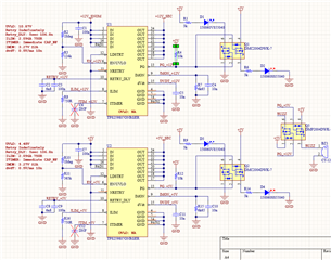
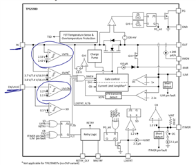
I am using TPS259807ONRGER to monitor and switch off 12V and 5V rails when there is a short circuit.
My scenario is as follows:
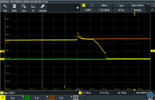
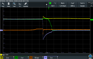
  When there is a short circuit the eFuse will shut off the power and then retry to turn on after 5seconds
During this 5seconds the PG signal will go low and trigger a buzzer.
After 5seconds pass, eFuse will try again and if there is no short circuit the buzzer will be off.

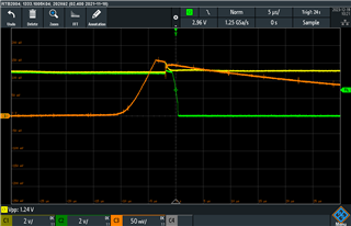
12V rail works as expected, but 5V rail do not perform the 5second delay.
I checked the RETRY_DLY pin,  there is 90ms second period oscillation for the 12V rail.
But there is only DC on this pin for the 5V rail.
After repeatedly shorting 5V rail, the oscillations sometimes appear in that pin and therefore I have 5second delay.

Am I missing something or for 5V the oscillation does not start and/or unstable.
I will be greatful if you could help me.

Kind regards

  • Hi Kerem,

    What are you getting at output when 5V rail is not performing the 5second delay. Can you probe Vin, Vout, Input current for scope shots. Check if it is stable at 5V, if it drops below 4.48V then it will basically reset the EN pin which will turn the device on again. You can do this for 12V rail also, so we have some data for comparison. 

    Best Regards,

    Arush

  • Hi Arush,
    Thank you for your message.
    When the eFuse does not perform the 5second delay, it starts conducting after the short circuit is released.
    I get the power from a PC power supply, so I don't expect voltage dropping on the rail.
    And I forgot to mention that I shorted the EN pin to the 5V rail. So the the UV of 4.48V threshold does not apply.
    For testing, I short out output pins to ground. The main task of the circuit is to avoid any accidental short circuits.

    It looks strange to me that I see oscillation on the RETRY_DLY pin sometimes with the 5V eFuse, but always for the 12V eFuse.
    Could there be something else that I am missing?

    Best regards

    Kerem 

  • Hi Kerem,

    Can you provide me with some waveform of Vin, Vout, Input current (if possible). When you create a short at output, the inrush current can be huge and will cause drop in power supply voltage. Let's try this please. I want to first eliminate other possibilities before thinking about the oscillations you mentioned.

    You also mentioned that 5V sometimes works. I feel that when do manual hard short, it is not same during every try. Sometimes the supply drop is less, sometimes it is more.

    Best Regards,

    Arush 

  • Hi Arush,
    I checked the voltage drop on short circuit event. 
    You are correct the voltage drop is quite large. I can not provide any unfortunately.
    Then I added a 22uF cap at the input terminal.
    The following is the 5V input and the PG output. the DC output is the RETRY_DLP output.

    Best regards

    Kerem

  • Hi Kerem,

    • Please label the waveforms. Can you tell me color to signal legend in the above waveform.
    • Do you any other power supply. You can try using external power supply at EN to prevent power reset and you should get 5s delay after this.
      • This will remove UVLO but you will still get UVP (under voltage protection at around 2.42-2.53V)
    • What is the end application. At what stage of development are we at?

    Best Regards,

    Arush

  • Hi Kerem,

    Were you able to resolve the issue by using external power supply for EN pin? 

    Please reply here if any further questions. 

    Best regards,

    Arush

  • Hi Arush,
    I am sorry for the late reply. Thank you very much for your message.
    Our application is a test measurement equipment. And the power from the PC power supply is distributed via a non functional PCIe (no PCIe connections but is plugged into the PCIe slot) board to the whole test measurement system.
    Sometimes the power connector coming from this PCIe board is accidentally short circuited.
    The eFuse that I use serves this purpose.

    On the wafeform image:
    The yellow trace is Power Good
    Orange trace: the input Voltage. Therefore ENABLE pin. I shorted EN pin to VIN.
    Green is the REPLY_DLY pin.

    When I look at the traces the 5V power rail does not drop at all below EN pins threshold.
    This makes me believe an issue not related to ENABLE pin dropping too low.
    As I mentioned the ENABLE pin is directly connected to the power rail 5V.

    Unfortunately I can not use any other power supply, because there are 2 power rails 12V and 5V and I need to protect both from short circuits from downstream devices.
    I need to connect the ENABLE pins to the power rails directly.
    Kind regards

    Kerem


  • Hi Kerem,

    I will get back to you regarding this by Friday.

    Best Regards,

    Arush

  • Hi Kerem,

    I have few questions and observations.

    • Why is your input/enable signal (Orange) clamped at some level lower than 5V before the trigger and then going back to 5V. What was the test you did for this waveform capture. 
    • Your PG (yellow) signal is going low, so that means issue is in Vin.
    • Can you please provide Vin and Vout in the waveforms. RTRY_DELY is not helping much. 
    • Can you try probing IMON so that we can figure out the current.

    Best Regards,

    Arush

  • Hi Arush,
    Thank you very much for your email.
    I tried to capture the waveforms that you requested.
    This board has a DSub connector, I connect a 1 meter long cable to this board. And at the other side of the cable I short the 5V rail to GND.
    The EN pin is again connected to the 5V rail directly.


    Yellow: Vin
    Green: PG
    Orange: IMON
    Purple: VOUT

    I connected a 47u and 10u Electrolic cap on the power rail input connector. And this is really close the eFuse Chip.
    IMON output shows different behaviours like this:


    It is sometimes quite high, sometimes low on short circuit trigger.

  • Hi Kerem,

    I will reply back to you by Thursday EOD. I have multiple bench testing which are taking all of my time for now. 

    Thank you for understanding,

    Arush

  • Hi Arush,
    Happy new year. I haven't heard from you related to the problem that I was having.
    Were you able to look at the issue?
    Kind regards

  • Hi Kerem,

    I am sorry for late reply and wish you a very happy new year.

    I noticed few things. 

    1. You don't have transient protection in your system. I didn't know that your application has very high wire inductance at input and output. During events like hot-plug at input and short ciircuit at output, transients can violate the absolute range of the efuse. Here in the first waveform, we can see absolute minimum violation for efuse. Please refer section 10 in datasheet and consider including schotkey diode at output to prevent absolute minimum violation.
    2. PG signal is going low due to Vin - Vout  > 3.6 (PGTH) for the device and not because of Vin issue. 

    Let me think what else can reset the device which is preventing the 5second delay before retry. Do you have any hypothesis? Retry pin oscillation part can indicate the retry logic but not the cause of no delay. Do you have any old waveforms (good retry, etc.)

    Best Regards,

    Arush

  • Kerem,

    I had a discussion with my colleague. He mentioned that negative Vout sometimes resets the efuse which is causing this issue of no retry delay.

    Please include TVS diode at input and Schotkey diode at output and some higher value (in uF) ceramic capacitor at input and output. I am including the part number from our EVM. You can also refer to BOM/schematic from EVM user guide. 

    Best Regards,

    Arush

  • Dear Arush,
    Thank you very much for your message and all your efforts in providing a solution to my problem.
    The PCB is located inside the PC and it gets power directly from the PSU of the PC with a relatively long cable around 30cm.
    To be honest, I didn't expect cable length to create a problem.
    I will follow your advice and add relevant parts to my circuit for both rails +12V and +5V.
    I hope this resolves my problem.
    Best regards

    Kerem