This thread has been locked.

If you have a related question, please click the "Ask a related question" button in the top right corner. The newly created question will be automatically linked to this question.

BQ79656-Q1: Noise issue in BQ79656-Q1 stacked with BQ79616-Q1

Part Number: BQ79656-Q1
Other Parts Discussed in Thread: BQ79616-Q1,

HI

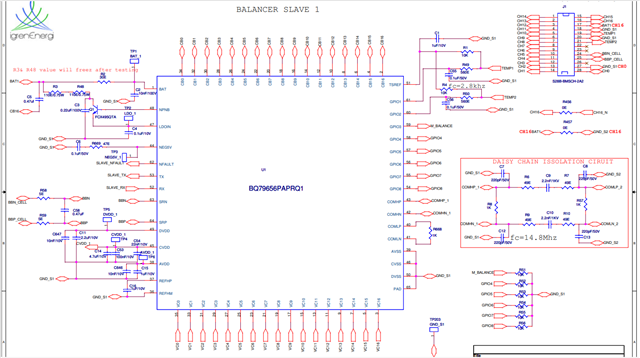
Our BMS system consist of BQ79656-Q1 as base device and six BQ79616-Q1 devices.

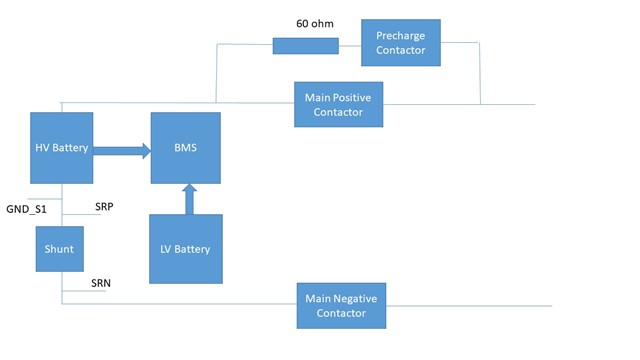
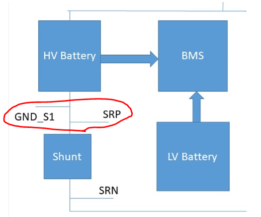
We have connected HV battery with shunt current sensing, charge-discharger and contactors.

There are three contactors

Positive line contactor, precharge contactor and negative line contactor.

The base device communicate to host MCU over UART lines and using isolator ic ISO7342.

During precharging, we are seeing that BQ79656-Q1 is alone going into sleep mode without giving any sleep command.

Other slaves are not going into sleep.

This is leading to Daisy communication fault.

We have given wake up repeated commands to keep it in wake state, however there is still a daisy communication fault.

Some observations:

1. BQ79656-Q1 is going into sleep mode during the turning on of the contactors and charger connected.

2. if charger is not connected and the base device is not going into sleep.

3. If shunt is disconnected then also sleep mode is not getting activated.

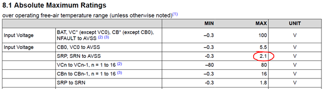
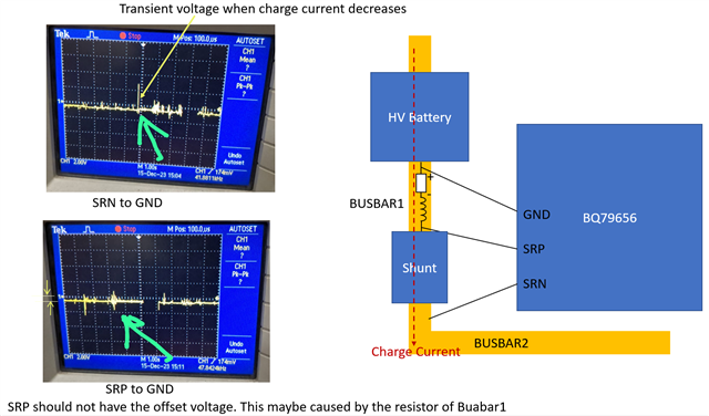
So from above observation we are suspecting that some noise is entering through SRP and SRN lines through charger after turning on the contactor.

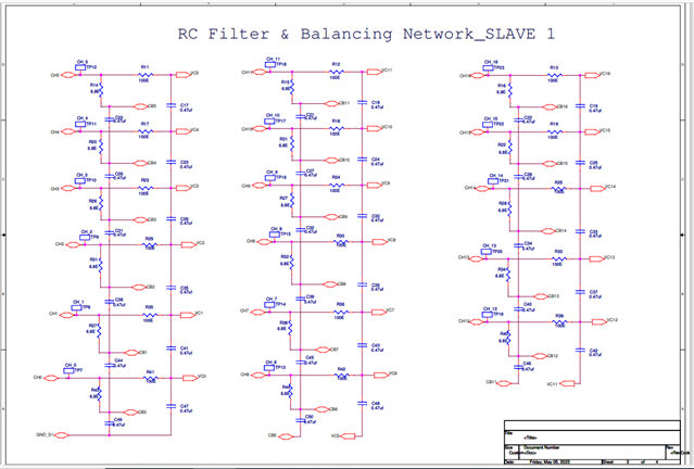
However, we have 10 ohm two resistors and 0.47uF capacitor in SRP and SRN line.

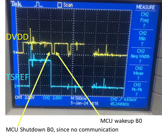
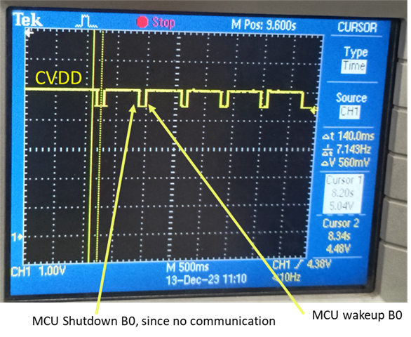
During this interruption CVDD is falling from 5V to 4.3V and DVDD is falling from 1.8V to 0V.

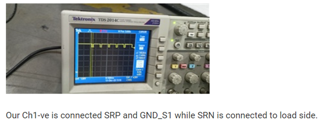
The below waveform is of CVDD. It falls down from 5V and goes to 4.3 V.

Our Ch1-ve is connected SRP and GND_S1 while SRN is connected to load side.

Can you please tell us how to get rid of this noise?

Can we use higher value of resistances and capacitances in SRP and SRN line?

Can we try to add ferrite bead in addtion?

What is getting affected in IC due to noise that it is going into sleep state without hardware command?

Thanks and regards,

Ramchandra Bhosale.

  • Hi,

    So it seems like this noise is causing an undervoltage error on the BQ79656 device. When the voltage drops on CVDD to 4.3-4.65V that is low enough to trigger an undervoltage event. When DVDD undergoes an undervoltage event, a digital reset is triggered, which could be what is happening here. After going to sleep does the device wake up again? You described a filter for each of the SRN/SRP pins; is there a capacitor between the two pins? This can help with common-mode noise. If possible, can you share the system schematic? 

    Best,

    Nancy

  • After going to sleep the device does not wake up on its own.

    If we give repeated wake up signals then only it wakes up.

    Yes there is a capacitor of 0.47 uF between SRP and SRN lines.

    I am sharing the relevant diagrams here.

    Do you need any DSO waveforms for more information?

    Do you have any support system based in INDIA which can support during IST timings?

    Thanks 

    Ramchandra Bhosale.

  • Hi Nancy

    Waiting for your response.

    Can you give us some way to identify and debug the mentioned issue ??

    Thanks and regards

    Ramchandra Bhosale

  • Dear

    As this is a very concerning issue for us, and we are nearing the end of the release phase of Our BMS. We would appreciate it if you could prioritize our inquiry; we understand that it is the end of the year and the holiday season, but this is a major concern for us. In your absence, I would appreciate it if you could delegate this task to someone else, preferably someone from the Indian standard time zone.

  • Hi,

    Apologies for the delay and thank you for the additional information. I have a couple more questions:

    1. What do you observe on the TSREF pin during this unexpected behavior? Do any of the other supply rails (AVDD and DVDD) exhibit similar behavior?

    2. What is the value of the register COMM_TIMEOUT[CTL_ACT]? This register controls the communication timeout feature. 

    Thanks,

    Nancy

  • Dear

    COMM_TIMEOUT[CTL_ACT

    It is 1, we have set CTL and CTS as 2s and on timeout we want device to shutdown, but we have checked on DSO the communication is active i.e; the data is always transmitted on 10ms interval from master MCU. This activity is observed when HV contactor are triggered and Shunt resistor is connected. Also the problem that i am facing from sw/fw end is when we detect communication loss we try to Reset/shutdown the device and wakeup again to establish communication but still devices is non responsive it takes around 4-5 wakeup attempts to see response from BQ796xx. We have Checked shutdown and wakeup Code working on POR and MCU shutdown and both work correctly on MCU command trigger to BQ796xx. But when ever this fault occurs we are forced to send multiple wakeup to see any response from BQ796xx. Also it would be better if you can add as many debug or diagnostic point for analysis in one request as our team will have to travel 120KM to collect data for analysis, so please point all the query in single request.

    Also we tried to debug to see any shutdown/sleep command from firmware end but was not observed on debug.

    Please try to Assign someone from IST zone to resolve this issue.

  • Hi Ramchandra,

    I am able to connect you with an engineer based out of China. Can you friend me on E2E so we can begin communicating via email? Emails cannot be shared on a public forum. 

    Best,

    Nancy

  • Ok I have done it so. 

    I am also sharing Tsref and DVDD waveforms here.

    It goes down without giving sleep command.

    Blue - Tsref and Yellow - DVDD

  • Hi,

    I see the voltage of SRP to GND_S1 is about 6V. It is much higher than AMR 2.1V.  

    I think it should be a very low voltage. Why the voltage is so high?

  • Hi Harrison

    As I had mentioned the waveform shown in the above image is CVDD which falls from 5 V to 4.3 V.

  • "Our Ch1-ve is connected SRP and GND_S1 while SRN is connected to load side."

    What does "Ch1-ve" mean?

  • Hi Harrison 

    -" Ch1-ve " means HV-ve of the battery.

    In other words negative terminal of the high voltage battery.

  • It seems the SRP and SRN‘s noise related. Could you capture the waveform of SRP to GND and SRN to GND when 656 goes to sleep.

    Try to disconnect SRP or SRN for confirming which wire is causing the issue.

    The under voltage of AVDD and DVDD will cause 656 reset. You can capture the waveform of AVDD, DVDD and LDOIN. 

    Increasing impedance of  SRP and SRN is one solution. I suggest first confirm the root cause, then give detailed solutions.

  • Hi Harrison,

    Ok We will disconnect SRP or SRN one by one to see through which line noise is entering.

    We have already shared the voltage waveforms related to AVDD, DVDD and LDOIN.

    Can you please see the previous response to see the waveforms?

    We have captured SRP and SRN waveforms which are as follows::

    SRN wrt to GND_S1

    SRP wrt GND_S1

    SRN wrt to GND_S1

    SRP wrt to GND_S1

    We have increased the input filter resistance of SRP and SRN upto 10 ohm but we are still getting same fault.

    How should we increase the impedance of SRP and SRN lines?

    Thanks and regards,

    Ramchandra Bhosale.

  • Increasing the impedance of SRP and SRN will increase the sampling error. You can try higher resistance and capacitance, just to verify if it works. We then evaluate the impact of the feasible RC. 

  • Hi Ramchandra,

    I think the MCU shutdown and wake up B0 repeatedly caused this waveform. 


    The question is why the communication loss? I guess the noise on the GND flipped the data on the UART, causing communication failure. MCU can send COMM CLEAR when there is no noise, observe whether communication can be recovered. During debug, CTL and CTS must be disable.

    The MCU continuously monitors the fault status in order to indicate whether the FAULT_SUMMARY have fault.

    If SRP/N noise is conducted to GND, it may affect UART communication.

    The following analysis is my guess. Check the  length and resistor of BUSBAR1.

  • Thanks Harrison

    I will try to reduce the distance between SRP and GND and reverify. I have some doubts related to it.

    If flipping of the UART line is causing communication loss, then should it causing base device to go into reset/sleep mode?

    What is the expected behaviour with other balancer ics?

    As per our observations other balancer ics are not going into reset or sleep mode?

    Do you think BQ79600 based circuitry will help as it communicates over comh and coml line and not over UART lines?

  • Datasheet says "To avoid collisions during data transmission up the daisy-chain interface, the host must wait until all bytes of a communication transmission are received from the device before attempting additional communication to the device. If the host starts a transmitting without waiting to receive the preceding transaction's response, the communication is not considered reliable and the host must send a COMM CLEAR to restore normal communications to the base device."

    When B0 is waiting for the response frame form S1, the TX of B0 should be high. If there is a low level of TX, B0 will recognize a new command. Then B0 will enter “silent mode”. Because B0 thinks that the MCU is working abnormally. The best action of B0 is to send nothing and wait for the MCU to return to normal and send COMM CLEAR.

    So the flipping of UART will not cause B0 enter other mode. The CTL and CTS can cause B0 enter other mode.

    All the BQ796xx devices include BQ79600 have this feature. 

  • "To avoid collisions during data transmission up the daisy-chain interface, the host must wait until all bytes of a communication transmission are received from the device before attempting additional communication to the device. If the host starts a transmitting without waiting to receive the preceding transaction's response, the communication is not considered reliable and the host must send a COMM CLEAR to restore normal communications to the base device."

    Dear Harrison, MCU waits for 20ms before sending any other request to BQ796xx or wakeup on failure. After every Request, wait time is 20ms, since we are working 1mbps baudrate this time more than adequate.

    The CTL and CTS can cause B0 enter other mode.

    We have set CTL and CTS to be 2s, and Shutdown on timeout.

    The major issue from firmware end for us it whenever this fault occurs it requires us to send multiple shutdown and wakup sequence to see any response from bq796xx. as you can see on oscilloscope record there are multiple wakeup sequence as bq796xxx is unresponsive. THIS IS CONCERNING PART.

  • "Dear Harrison, MCU waits for 20ms before sending any other request to BQ796xx or wakeup on failure. After every Request, wait time is 20ms, since we are working 1mbps baudrate this time more than adequate."

    I guess the noise on TX caused B0 to think that there is a new command.

    "The major issue from firmware end for us it whenever this fault occurs it requires us to send multiple shutdown and wakup sequence to see any response from bq796xx. as you can see on oscilloscope record there are multiple wakeup sequence as bq796xxx is unresponsive. THIS IS CONCERNING PART."

    If there is continuous noise, It is possible that communication cannot be reached. Therefore, when communication fails, stop charging or discharging. Make the pack current is 0A. Then MCU send COMM CLEAR. If it doesn't work, send wake up.

  • Dear Harrison,

    I guess the noise on TX caused B0 to think that there is a new command.

    TX is not LOW, its always HIGH you can see in DSO captured images.

    If there is continuous noise, It is possible that communication cannot be reached. Therefore, when communication fails, stop charging or discharging. Make the pack current is 0A. Then MCU send COMM CLEAR. If it doesn't work, send wake up.

    We havent yet passed the current its always 0. the current cycle is not initiated yet. It would be better if you can arrange a Skype/zoom call, I believe you are misunderstanding our concern. Your response are not in sync with what we are conveying.  I have repeatedly said in this thread we have observed even with multiple wakeup, the bq796xx doesnt respond.

    It is better if you can get in touch with over a virtual call/meet.

  • If wake up does not work, send hardware reset. Register CONTROL2[SEND_HW_RESET] = 1.

  • Contact FAE and use webex to contact me.