This thread has been locked.

If you have a related question, please click the "Ask a related question" button in the top right corner. The newly created question will be automatically linked to this question.

UCC28180: PFC

Part Number: UCC28180

I am using UCC28180DR for PFC but maximum PF i am getting is 0.8 @ 300W and iTHD 60%. Circuit is built for 1000W but it shuts down at 300W load, with high temperature of 105deg observed on FET. 

Requesting support in resolving.

  • Hello Brijesh,

    Thank you for your question regarding the UCC28180 PFC controller. 

    For a 1000-W design, there is definitely some problem when PF is 0.8 and iTHD is 60% at 300W.  The shutdown at 300W is also a concern. 
    I need more information about your design before I can help you to debug it.  

    Please provide a schematic diagram of the PFC circuit (preferably as a .pdf file) and fill out the UCC28180 Excel Design Calculator: https://www.ti.com/tool/download/SLUC506 .
    These will help me assess your design and possible find some issues that account for the behavior. 

    On your end, please check all of the components on your PFC board and make sure that the parts on the board match the parts on the schematic. 
    Sometimes the wrong part gets loaded onto a board, or a part is installed backwards, even when the schematic is completely correct. 

    Regards,
    Ulrich

  • Hi Ulrich,

    Design calculation is done using same calculator. Checked all the parts its as per schematics.

    01_PFC BOOST.pdf

    Attached Schematic.

    Regards,

    Brijesh

  • Hello Brijesh, 

    Thank you for the schematic diagram, it is very helpful.  
    I also request for you to post your calculator file, please. 

    There are two circuits attached to the PFC section that may interfere with normal operation.
    The first is the Active EMI filter.  For debug purposes, please remove coupling capacitor C25.  Although I doubt that this circuit can cause the trouble that you are experiencing, I'd like to be sure there are no unexpected external effects to the main PFC operation. 

    The second is the UVP & OVP circuit.  For debug purposes, please remove PFC_OFF transistor Q2. 
    Either of these protection circuits may be interfering with the feedback sense and power level capability.

    If your PFC runs properly with those components removed, then add the C25 back first.  If it doesn't work, the debug the EMI filter.
    If the PFC does still work, then add Q2 back.  If the PFC malfunction symptoms return, then please debug the UVP and & OVP circuit functions. 

    Regards,
    Ulrich

  • 0118.sluc506c.xls

    H Ulrich,

    Attached calculation sheet. Removed Active EMI and UVP/OVP connections, now only PFC circuit still problem is same. Getting PF 0.8 and iTHD 60%.

    Used coil core is sendust, 90 turns and 1.2mH even at 100kHz.

    Regards,

    Brijesh

  • Hello Brijesh, 

    Thank you for the Excel file, it is helpful. 

    It shows that you are using a 5mR current-sense resistor where the tool recommends 25mR.  The signal level will be too low.  It also recommends to decrease from 25mR to avoid saturating ICOMP at 6V and the highest value that achieves that is 16mR.  Please increase R87 and R109 to 0.033 each. 

    If that does not fix the problem, please provide waveforms of the input current VCOMP and ICOMP.

    Regards,

    ULRICH

  • Hi Ulrich,

    Changed Current Sense resistor 10mR according to calculator, but this didnt helped. VCOMP voltage is not changing according to load wrt calculator.

    Regards,

    Brijesh

  • Hello Brijesh, 

    At this point, I am unable to diagnose the problem with just descriptions and the schematic alone.
    Please provide the waveforms that I requested:  Input current, VCOMP, and ICOMP.

    Thank you,
    Ulrich

  • Hi Ulrich,

    We have received waveforms from customer.
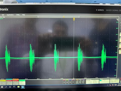
      (VCOMP waveform with PF correction)

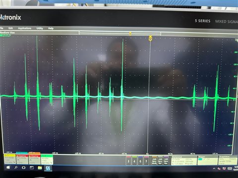
      (VCOMP waveform when PF correction stopped)

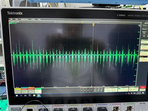
      (ICOMP waveform at PF correction)

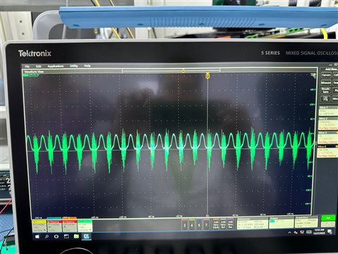
      (ICOMP waveform when PF correction stopped)

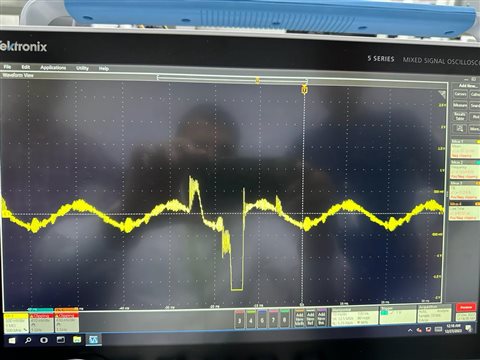
      (Input current 100W PF=0.3W)

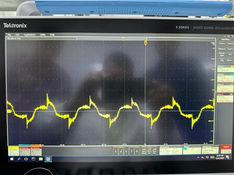
      (input current 70W PF=0.7)

  • Hello Kartik, 

    I have to admit, these are extremely strange waveforms.  Unfortunately none of them have enough information to allow me to come to any conclusion.

    VCOMP with PFC has huge amounts of noise every 20ms.  Noise pickup from a long GND lead on the oscilloscope probe may account for that, but I would have expected it to recur at 10ms intervals, not at 20ms.   

    VCOMP without PFC has quiet intervals lasting almost 120ms.  What is the PFC stage doing during this interval? 
    What kind of load is on the PFC converter?  An E-load? Resistor? Down-stream DC-DC converter?  What are the input and output conditions? 

    ICOMP with PFC appears to be almost normal at first, except with a lot of noise (this time at 10ms zero-crossings).  But closer look shows that the amplitude is about 23V! (half a division at 46V/div.)  This is not possible, since the controller would be irreparably damaged at 23V.  
    ICOMP without PFC is even worse at > 46Vpk, and apparently in half-wave operation.  
    I can't believe that these are ICOMP signals, unless they are amplified somehow or the display scale is wrong. 

    The input current waveforms have a scale of 500mV/div.  Can you please convert them to A/div, so I can assess their magnitudes with respect to the expected load and input voltage?  I have a suspicion that the sinusoidal parts of the currents are due to the EMI filter X-caps, not load current.  Except for the distortions, which do contain current that makes it through to the load. 

    All of these waveforms are presented individually, without context of relationship to other signals in the converter.  There is no reference to the zero-crossings of the rectified input; no GATE signal information; no Vout waveform; no MOSFET waveform, and no indication as to what causes the extreme noise bursts every 20ms.  The oscilloscope is capable of accepting 8 channels, so I think it would be very useful to display several signals at the same time to see what might be happening in different parts of the circuit during the strange operation.  I suggest to use normal scaling (like 5V/div, 10V/div, 1A/div, etc.) instead of unusual scales like 46V/div and others like that.

    I don't see anything in the schematic diagram that could account for the waveforms shown so far.  Therefore the problem(s) must be on the prototype board being tested.  Look for solder-shorts, open circuits, or backwards components.   Perhaps debug might be improved if a DC input were provided to the PFC.  It should be have exactly as a DC boost converter. 
    Test at low power levels, and vary the DC slowly to see what effect changing voltage has on the output and on the various waveforms.   

    Regards,

    Ulrich

  • Hi Ulrich,

    We are able to solve the issue and the board is working fine. Thanks for the support.

    Regards,

    Brijesh

  • Hi Brijesh, 

    I'm glad that you were able to solve it.  Thank you for letting me know.
    I will close this thread.

    Regards,
    Ulrich