

Other Parts Discussed in Thread: TPS54201
I'm trying to build a resistive heater, but only have some LED drivers available.
It feels that only putting a resistive load on a LED driver is not a good idea. But I would like to understand what happens.
In the case of the TPS92200 the feedback pin VFB is fixed at 99mV. What if I would match that with a voltage divider? So if R1 is connected to the SW output and R2 connected to R1 and VFB, like shown in the picture below.
Unfortunately there is no spice model available for the TPS92200, but there is one for the TPS54201.
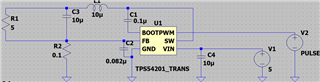
In theory: Rtotal = 5+0.1 = 5.1Ohm, and to get a 0.1V over R2 we should have about 5.1V on SW and get 1A through the resistors.
VR2 = 0.1 (99mV)
VR1 = VSW has to be 5.1 as due to the voltage divider. VSW * (R2/R2+R1) = 0.1
I = 5.1/5.1 = 1A
Something doesn't feel right and the simulation kind of concluded that. It keeps running but nothing really happens.
Would adding a diode after the resistor be a solution or is there maybe another way to make a resistive heater.
Note: the 5 Ohm resistor will be a lot of resistors in parallel.
