Hi,
I've posted a few times regarding this chip and continue to have issues with it. I'm now at the point of looking at a viable alternative.
Previously the chip would self-destruct due to the phase issue. I've since found a combination which works across the input voltage range of 1V to 5V whilst giving reasonable current output without the chip self destructing. The issue now is one of regulation.
For the 61022 I have 22u 10v close by on the input side and 44u 10v for the output side. The input side also has 1500uF of solid polymer close by, and the output has a 220uF of solid polymer close by. The input source is two large super-capacitors which can sink many times the current the 61022 is able to draw.
The boost is set for 5V output. A 120p capacitor from the calc.xls is used and indicates the chip is stable at all current draws.
If the output current is too great there is a UVLO set for 4.5V. This will turn the output draw off until it recovers to 4.9V.
Here is the output circuit.
The output from the buck is a peak of 2A at 4V. So 8W, and factoring a 10% efficiency drop is 8.8W. Divided by 5V = 1.76A.
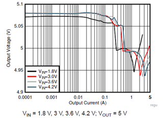
When this is requested with a 4V input the 61022 doesn't regulate to 5V and the UVLO fires at 4.5V, so the 1.76A is too great an ask.
My understanding is one can have wide operating input voltage with stability if the output current is quite low compared to the headline figure of 8A.
If there is any other understanding around this it would be good to know.
Regards
Alex

-
Ask a related question
What is a related question?A related question is a question created from another question. When the related question is created, it will be automatically linked to the original question.