This thread has been locked.

If you have a related question, please click the "Ask a related question" button in the top right corner. The newly created question will be automatically linked to this question.

TPS6594-Q1: TPS6594133A-Q1 Power calculation tool

Part Number: TPS6594-Q1
Other Parts Discussed in Thread: TPS62873-Q1, TPS62875-Q1, TPS62873

Hello sir,

Do you have below power calculation tools (such as excel or other format)? If yes, could you share to us, I would like to use them to evaluate power design as for reference?

  1. TPS62873-Q1
  2. TPS62875-Q1
  3. TPS6594133A-Q1

best regards

cynthia
  • Hello Cynthia,

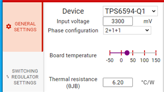
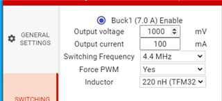
    There isn't a power calculation tool for the TPS6594133A specifically. However, the PMIC Efficiency Estimator can be used to calculate expected performance of the buck converters. The '133A uses a 2+1+1 phase configuration, 4.4MHz, and Forced PWM mode:

    https://dev.ti.com/gallery/info/PMIC/PMIC-Efficiency-Estimator-Tool

    Please create a separate post for the TPS62873 and TPS62875 devices.

    Regards,

    Mike

  • Thanks for your reply. I will create another post for TPS62873 and TPS62875 devices.

  • hello Mike,

    for TDA4AL application, this mode “133A select 4.4MHz, and Forced PWM mode" is ok? If select 2.2M, what's the impact for PMIC efficiency evaluation?

  • Hello Mike, 

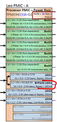
    Another question, according to TPS6594x-Q1 datasheet, LDO 1, LDO2, LDO3 current capacity are 500mA, but in PDN-7F, why is marked with 165mA for LDO2? It makes me confused.

  • for TDA4AL application, this mode “133A select 4.4MHz, and Forced PWM mode" is ok? If select 2.2M, what's the impact for PMIC efficiency evaluation?

    The '133A is configured with 4.4MHz FPWM mode. Changing to 2.2MHz would require a new NVM or custom part number. 

    Another question, according to TPS6594x-Q1 datasheet, LDO 1, LDO2, LDO3 current capacity are 500mA, but in PDN-7F, why is marked with 165mA for LDO2? It makes me confused.

    That appears to be a typo in the diagram. 500mA is the capacity of LDO2. The 165mA might represent the expected max current pull on that rail for the PDN. 

  • "The 165mA might represent the expected max current pull on that rail for the PDN. ", Could I understand that LDO2 max output current is 165mA for J721S2 PDN-3F solution, and if this power rail exceeds 165mA, LDO2 will be damaged? 

    But I still can't understand, where is from 165mA? How to define this value 165mA to LDO2? What's the difference from TPS6594x datasheet parameters? Is specific current value settings in NVM for TPS6593133A LDO2?

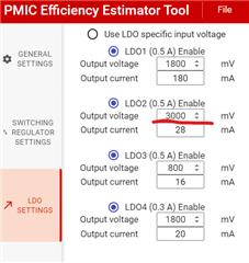
  • Another question, when I use https://dev.ti.com/gallery/info/PMIC/PMIC-Efficiency-Estimator-Tool, By pass LDO2 output can't select to 3.3V, what's the reason?

  • "The 165mA might represent the expected max current pull on that rail for the PDN. ", Could I understand that LDO2 max output current is 165mA for J721S2 PDN-3F solution, and if this power rail exceeds 165mA, LDO2 will be damaged? 

    But I still can't understand, where is from 165mA? How to define this value 165mA to LDO2? What's the difference from TPS6594x datasheet parameters? Is specific current value settings in NVM for TPS6593133A LDO2?

    PMIC LDO2 can be configured as an LDO or Bypass load switch. When TPD6594133A powered by 3.3V source on VCCA, it automatically configures LDO2 to function as a load switch. When powered by 5V, it acts as an LDO. As an LDO, it can supply up to 500mA while maintaining DC accuracy specs. The current limit is 700mA to 1800mA depending on mode, temperature, and input-output combination. 

    LDO2 will NOT be damaged if it exceeds 165mA. I believe the 165mA in the block diagram is a typo. 

  • Another question, when I use https://dev.ti.com/gallery/info/PMIC/PMIC-Efficiency-Estimator-Tool, By pass LDO2 output can't select to 3.3V, what's the reason?

    When configured as an LDO, LDO2's dropout voltage is 300mV. The tool will not let you select an output higher than 3V when the input is set to 3.3V. 

    For the TPS6594133A with a 3.3V input, LDO2 is a load switch. Maximum power loss can be estimated using the bypass resistance in the data sheet. 

    ...