- Ask a related questionWhat is a related question?A related question is a question created from another question. When the related question is created, it will be automatically linked to the original question.
Hi, this is my first post here. I have some experience designing around Arduinos and ESP32's, but this is my first design with PoE and the TPS2378.
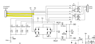
Basically, i've been told that jacks with CTs on the "board-side" are useless for PoE, such as this one (P4 and P5):

And instead, they need to be connected like this (R8 & R7):
Is that correct? Having some trouble wrapping my head around this. If so, this means that this HR861153C below is a Mode B-only jack? Since wires 4,5 & 7,8 go to the rectifiers, and only "board-side" CTs connect to the rectifiers (Mode A, but board-side?)?