This thread has been locked.

If you have a related question, please click the "Ask a related question" button in the top right corner. The newly created question will be automatically linked to this question.

TPS2121: Output shut off during switchover in XCOMP mode

Part Number: TPS2121
Other Parts Discussed in Thread: TPS62135

We are using the circuit below. Not that there is >100uF on the IN2 and OUT nets on another page. IN1 is connected to an AC power brick, and IN2 is connected to a PoE module. Both have a nominal voltage of 12V. The power brick (IN1) has priority when its voltage is > 10.8V. 

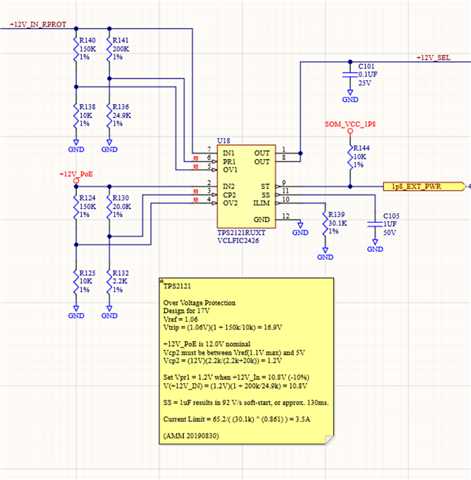
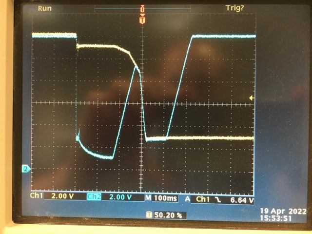
We thought that this was working, then discovered that when AC power is removed from the power brick attached to IN1, the output drops for over 100ms.  During this time, IN2 remains stable. Current draw is approximately 1A. See the plots below.

  • Ch1 (Yellow) IN1

  • Ch2 (Blue) OUT

We have tried several things:

  1. Added 100uF to 2200uF to IN1. This seemed to reduce the problem, but did not eliminate it.
  2. Switched to VCOMP mode. No improvement.
  3. Increase current limit to max. No improvement.
  4. Eliminate OV protection. No improvement.

It looks like the TPS2121 initially goes into some kind of protection mode for 15ms, then seems to shut off internally. During this time there is a lot of noise on IN1, which seems to indicate that something is oscillating. When the TPS2121 turns back on, it has still selected IN1, and doesn't switch to IN2 until 400ms after IN1 drops below the threshold.

What can I try next?

Thanks,
Andy

  • Andy,

    We are looking into this, however given the holiday in the US it's going to be next week until we can get a handle on what the problem might be here.

    What exactly are you using on the load side? Are you using an actual discrete load or something like an eLoad?

    Best Regards,
    Tim

  • Timothy,

    Thank you for the response. The load is several DC-DC converters (mostly TPS62135) and fans. Therefore, current will increase as the voltage decreased.

    Have a Happy Holidays.

    Andy

  • Hi Andy,

    Thanks for your patience on this. It looks like what may be happening is IN1 is dropping to 10.8V (PR1 trigger point) and, when the device switches to IN2, IN1 voltage raises a little bit and reenables IN1, and the cycle continues hence the oscillations.

    I would recommend adding hysteresis to PR1/CP2 by attaching a resistor from PR1 to ST. There is a calculator at the bottom of this FAQ that can help determine a good resistor value.

    Also I'd like to note that your PR1 resistor divider is using rather large values. If the resistors are not placed very close to the device, this can cause the device to either switch after IN1 drops or oscillate between IN1 and IN2. However, I would recommend lowering these resistor values in conjunction with the first recommendation if adding the hysteresis resistor does not help.

    Thanks,

    Patrick