This thread has been locked.

If you have a related question, please click the "Ask a related question" button in the top right corner. The newly created question will be automatically linked to this question.

LM5143: Timing of Vin and enable pin

Part Number: LM5143

Hi team:

 My customer using LM5143 and found some funny issues.

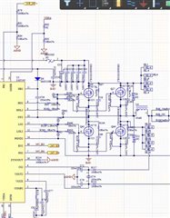
1. 48Vin, 24V(Channel2) & 10Vout

2. If the Enable  signal takes precedence over Vin, Channel 2  of 24V will becomes 5V. and seems go into protection mode?   Channel 1 of 10V works well.

Green : EN

Blue: Vin

Purple: 24Voutput

Tks for your checking.

  • Hi Allen,

    Send on a completed quickstart file for this, so we can review the design.

    Check the Thevenin resistance of the feedback network, as it must be > 5kΩ (otherwise it will detect FB low at startup and configure as a fixed 5V output). Also, I see the output is dipping negative right before EN going high, which may also be affecting this.

    Regards,

    Tim

  • Hi Tim:

     tks for the comments. Due to not release product, only few area  SCH can be share:

    and we can see is that the Thevenin resistance of the feedback network > 9kΩ, would you share your insight and can you reproduce on your lab? 

    tks for the checking.

     8422.LM(2)5143-Q1 quickstart design tool - revB2.xlsm

  • Hello, The responsible engineeer is out of office now. TI responses may be delayed during the end year Holiday Season until Jan 2nd, 2024. Thank you for your patience.

  • Allen,

    Go ahead and investigate Vout going negative just prior to the EN startup. This is the main difference relative to the VIN startup and likely causing FB being detected as low.

    Here are some comments on the design:

    1. 45uH inductance on the 24V output is way too high and only gives 4% ripple current (not good for slope compensation either).
    2. 5uH is slightly low on the 15V output, giving 45% ripple (30-40% is the target).
    3. No need for 100Ω on VOUT2 as it may cause a voltage drop given the bias current into that pin.
    4. 10nF filter cap from CS2 to VOUT2 seems high and may cause a high RC time constant (too much filtering on the current-sense signal).
    5. No need for low-side FET antiparallel diodes, as the deadtime is so short.
    6. Use one current sense resistor (two in parallel may create sensing errors).
    7. Check that the output caps if ceramic are appropriately derated for voltage, as this affects compensation.
    8. 39.3kΩ and 2kΩ on the 12V output does not meet the 5kΩ Thevenin impedance rule. Increase by at least 3x.

    --

    Tim