This thread has been locked.

If you have a related question, please click the "Ask a related question" button in the top right corner. The newly created question will be automatically linked to this question.

TPS65987EVM: USB PD

Part Number: TPS65987EVM
Other Parts Discussed in Thread: TPS65987

I have a requirement for the EVM kit to sink the maximum power possible from a source connected to it on it's type-C port. I am powering up the EVM kit with a 65W capable type-C adapter but the USB VBUS is not negotiating the PD requirement and it is not increasing above 5V. 

Is there any default configuration that we need to change in EVM for it to sink more than 5V 3A (>15W). If yes, then is it required to be done from Hardware or the GUI tool?

Currently the Jumpers J4 and J5 are kept at their default positions. 

  • Hi Rutvik,

    Do you have a .pjt file that I may be able to look at? This is developed from the application customization tool (or GUI) which can be downloaded from the TPS65987EVM product page.

    You may need to change the Source/Sink PDOs to be able to meet these increased levels if you haven't already. Which is also done through the ACT/GUI. 

    Using the .pjt and .bin file that I have included at the bottom of my response, that I set up, I was able to negotiate 5V, 9V, 15V, and 20V contracts as can be seen below:

    Currently the Jumpers J4 and J5 are kept at their default positions. 

    Would this be an accurate representation of the position of your switches and jumpers?

    PJT/BIN: TPS65987_Field.pjt, https://e2e.ti.com/cfs-file/__key/communityserver-discussions-components-files/196/TPS65987_5F00_Field.bin

    Thanks,
    Field

  • Thanks for the inputs. The EVM is able to sink 20V on USB VBUS now.

    Nevertheless I am facing a issue regarding PDO. Let me explain the PoC that I am trying to perform first:

    The requirement is to set the PDOs such that if the source connected to power up the EVM on USB type C connector is capable to deliver a maximum of 15W of power then the GPIO14 of PD controller should be enabled and the LED D22 should glow. Second case is if the source connected is capable to deliver more than 15W , then the GPIO20 of PD controller should be enabled and the LED D25 should glow. 

    The objective here is to implement a logic that my circuit only gets power when the source connected is capable to deliver more than 15W. Otherwise the power should not be delivered further.

    Also, according to the USB PD standards, only in the case of 5V on VBUS, the power will be less than 15W. For 9V, 15V & 20V, the power will always be more than 15W. So I have created only 2*PDOs. One for 5V input which should enable GPIO14; and the second PDO is for all the voltages other than 5V i.e. 9V, 15V, & 20V which should enable GPIO20.

    Now the issue I am facing here is that when I am connecting a type c power supply which is capable to deliver more than 15W power then the LED D25 glows as expected. But in the case when a source capable to deliver less than 15W is connected, LED D22 is not glowing.


    Please refer to the project file that I am using for your reference:
    TPS65987_Field_Demo3.pjt

    Let me know if you have any questions.

  • Hi Rutvik,

    When using your project (TPS65987_Field_Demo3.pjt) with the TPS65987EVM (as the sink) and TI's USB-C-PD-DUO-EVM (as the source) and selecting a 5V contract, so the <15W (PDO 0), the D22 glows for me as seen in the picture below:

    I am also able to establish a 9V, 15V, and 20V contract with the corresponding LEDs/diodes glowing, and as you described.

    Can you measure the VBUS levels when you do this and let me know what you find? When using your project file, and checking the VBUS TP1 I measured ~5V, during the above scenario pictured.

    Thanks,
    Field

  • Hello Field.

    Thanks for the prompt response.

    If you've successfully achieved the desired output, I assume the programmed digital outputs (PDOs) in the project file are correct.

    I've confirmed that the Voltage Bus (VBUS) reads 5V when connected to a source delivering less than 15W, indicating the voltage is within the expected range. The main difference in our setups is that I'm not using TI's USB-C-PD-DUO-EVM as the power source; instead, I'm using a basic USB to Type-C cable powered by a wall adapter.

    Could the wall adapter be insufficient to power the LED? Any suggestions for an alternative method?

    Is it possible that you replicate my setup at your end and check the status of LED? Kindly refer to the setup images below:

    Powering Up with 5V adapter (LED D22 not glowing):

    Powering up with 65W adapter (LED D25 glows):

  • Hi Rutvik,

    In this first picture you have, you are using a USB-A to USB-C. 

    In USB-A, the pinout for this does not contain the CC lines that are used to detect or negotiate the PDOs. There is an article linked here that covers and displays the pinout, but I have included a picture below:

    As you will notice the CC lines are not here. However if you take a look at the pinout for a USB-C, we can see these CC lines:

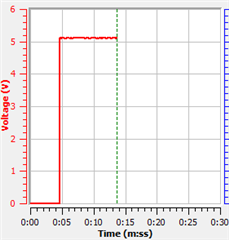
    This is why you won't see the LED light up, as even though we do see the 5V on VBUS like we are in PDO0 and as seen below (please note I stopped the program around 0:13s):

    But because there is no negotiated PDO0, the LED won't turn on because of this (based on the configuration of the GPIO), but as mentioned and as seen above and through measurement, you will see the levels on VBUS. And should correspond to your desires. There is also another article linked here that goes over some of what I discussed as well as others.

    Thanks,
    Field

  • Hello Field,

    Upon reflection, I've come to recognize my oversight. The LED is glowing when we connect the EVM with type-C to type-C cable. 

    This resolves my doubt. Thanks for  your support.