A related question is a question created from another question. When the related question is created, it will be automatically linked to the original question.
If you have a related question, please click the "Ask a related question" button in the top right corner. The newly created question will be automatically linked to this question.
Thanks for using the e2e forum. If I understand your observations correctly, this should not be an error.
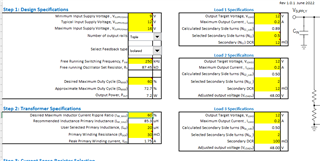
The winding ratios and output voltage results of load 2 & 3 are depending on the regulated rail, which is load 1. The flyback controller can only regulate one rail actively (load 1), the other two (or any additional winding) will be indirectly regulated via the winding ratio of the transformer. We have a lot of resources on flyback design in general. One example would be this app note: https://www.ti.com/seclit/ml/slup261/slup261.pdf