This thread has been locked.

If you have a related question, please click the "Ask a related question" button in the top right corner. The newly created question will be automatically linked to this question.

TPS92641EVM: The response is slow in SDIM drive when a resistor for offset cancellation is installed.

Part Number: TPS92641EVM
Other Parts Discussed in Thread: TPS92641

Thank you for your time.
Please let me ask you another question.

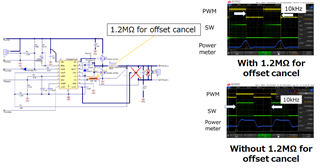
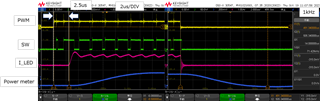
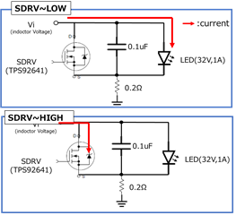
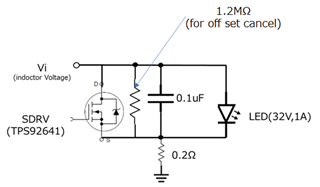
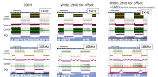
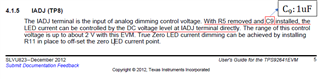
I'm currently using TPS92416EVM, but with the offset canceling resistor installed, the blinking speed becomes slower when driving SDIM. Please explain this mechanism.
Is it slow due to the time constant of Cout and R_offsetcansel?

Thanks

Takeshi

  • Hi Takeshi,

    May I understand what your input voltage, output voltage and output current are? Is there anything else that you have modified on the EVM?

    Best Regards,

    Steven

  • The parameter is input Voltage:48V、Output voltage:32V and Output corrent:1A. The components I have changed on the TPS92641EVM is shunt FET(NTD3055-150T4G) of Q3 for SDIM. These are in accordance with TPS92641EVM.

    Is it recomennded input PWM to SDIM when atacched 1.2MΩ for offset cansel?

    Best Regerds,

    Takeshi

  • sorry.
    I made a mistake in writing "This resolved my issu" below.
    The above figure is when driving with SDIM.

    The parameter is input Voltage:48V、Output voltage:32V and Output corrent:1A. The components I have changed on the TPS92641EVM is shunt FET(NTD3055-150T4G) of Q3 for SDIM. These are in accordance with TPS92641EVM.

    Is it recomennded input PWM to SDIM when atacched 1.2MΩ for offset cansel?

    Best Regerds,

    Takeshi

  • Hi Takeshi,

    • Is the above blue curve "Power meter" measured by a current probe and corresponds to the output current?
    • Please post the original picture of the oscilloscope capture. The above one is not clear.
    • Please also measure the inductor current and COMP pin voltage and show me the oscilloscope capture.

    Best Regards,

    Steven

  • >Is the above blue curve "Power meter" measured by a current probe and corresponds to the output current?
    →The blue curve is signal from Photo detector.

    >Please post the original picture of the oscilloscope capture. The above one is not clear.
    →Please show fig1

    >Please also measure the inductor current and COMP pin voltage and show me the oscilloscope capture.
    →As shown in the figure, the inductor is surface mounted, so it seems difficult to measure the inductor current.


    The fig2 is PMW for SDIM input mode I think. As for the figure, using shunt FET The Current can be swiched. So that, if the resistor(for offset cansel_fig3) is attached, the response will be slow. if the Shunt FET's capacitor is 0.1nF,the time constant will be 0.1n×1.2M=0.12ms.
    Are these explanation is correct?

          fig1.original picture of the oscilloscope capture


                       fig2.switching current on SDIM mode 

                     fig3. circuit attaching the registore for offset cansel

  • Hi Takeshi.

    Please measure the inductor current and COMP pin voltage and show me the oscilloscope capture. You can solder the inductor off the board and solder a wire to measure the inductor current. This will help me find out what's happening here.

    The fig2 is PMW for SDIM input mode I think. As for the figure, using shunt FET The Current can be swiched. So that, if the resistor(for offset cansel_fig3) is attached, the response will be slow. if the Shunt FET's capacitor is 0.1nF,the time constant will be 0.1n×1.2M=0.12ms.
    Are these explanation is correct?

    I need more information to judge if this explanation is correct.

    Best Regards,

    Steven

  • Please see the attached chart with measurements.
    From this figure, I had misunderstood. I would expect this delay to be caused by installing the capacitor(C_9) for IADJ, not by with the resistor for offset cancel.
    Do I still have to implement C_9 for IADJ to follow the datasheet?

  • Hi Takeshi,

    Thanks for the info. The thing is clearer now.

    When using the shunt FET, during the LED-off cycle, the output capacitor is discharged to almost 0V. During the LED-on cycle, the output capacitor is re-charged to the target voltage level (LED string voltage). The larger the output capacitance, the longer it takes for the output capacitor to be re-charged.

    When the C9 is not installed, the original output capacitor on the EVM is only 0.1uF (C5), which will not take much time when you re-charge the output capacitor when turning on the LED.

    When the C9 is installed, the output capacitor on the EVM is will be 0.1uF (C5) // 1uF (C9), which will take more time when you re-charge the output capacitor when turning on the LED. And this should be the reason why you see the slow response, especially in 10kHz PWM dimming condition.

    The thing is not related to the offset canceling resistor, R_OFF.

    Do I still have to implement C_9 for IADJ to follow the datasheet?

    I do not recommend using large output capacitance when doing shunt dimming as this large capacitance will greatly increase the LED current ramp-up time.

    Best Regards,

    Steven

  • I do not recommend using large output capacitance when doing shunt dimming as this large capacitance will greatly increase the LED current ramp-up time.

    ↑Why the datasheet recommend such a capacity(C9:1uF)? The reason is ripple curret to be removed for finely analog dimming?  

  • Hi Takeshi,

    ↑Why the datasheet recommend such a capacity(C9:1uF)? The reason is ripple curret to be removed for finely analog dimming?  

    I think you are referring to Section 4.1.5 from the EVM User's Guide. Although I am not the writer of this guide, I do have the same idea with you that the original writer wants users to install C9 to improve analog dimming performance in the condition that no shunt FET is installed, for two reasons:

    • Reducing output current ripple
    • TPS92641 works in forced CCM mode in low-output-current condition. There needs to be path for the current to flow even if the inductor current is negative. Consider you are not using any output capacitor (or small capacitor that do not provide small enough impedance path), the diode characteristics of the LED will not let the negative current flow. This will reduce the dimming linearity of the device. Use a larger capacitor will help and therefore improve the dimming performance / linearity. Hope my explanation can help. You can also refer to Section 7.3.4 Analog Dimming and True-Zero Operation from the datasheet.

    Best Regards,

    Steven