This thread has been locked.

If you have a related question, please click the "Ask a related question" button in the top right corner. The newly created question will be automatically linked to this question.

BQ79718EVM-049: BQ40Z50EVM-561

Part Number: BQ79718EVM-049

HI, I am working on 18S1P, Battery Bank with BQ79718EVM-049 as monitoring device, I am working on BQ79718EVM-049 single board for BMS application, I have connected BQ79718EVM-049 with PC through USB to Any interfacing device as per data sheet. VBat is set to be more than 30V as per data sheet, but device is not updating any parameter in software (BQ797XX 2.0.4).

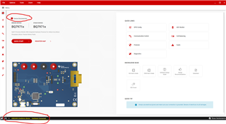
At the bottom left side of the monitoring software, it is showing that " USB2ANY/OneDemo device Hardware Connected", but at left top it is showing " Device Disconnected". (Screen shot is connected)
Please provide proper guidelines for using this BMS card,...

  • Hi Panjak,

    The bottom item that you've circled refers to the USB2ANY being recognized. It does not perform the WAKEUP and AUTOADDRESS sequence. You'll be able to perform these sequences within other parts of the GUI, for instance on the Quick Start page. 

    The "Device disconnected" is referring to the BQ79718 since you have not yet woken up and/or auto addressed the device. 

    Best Regards,

    Anthony Pham

  • Dear Sir, 

    I have done Auto address and wakeup multiples times, but still, it is not working.

  • Hi Panjak,

    Can you measure the voltages at AVDD and DVDD? I want to make sure that these are on so that they can power their respective internal circuits. 

    Best Regards,

    Anthony Pham

  • Hi, Anthony P Pham,
    following voltages, I found at said particular test points.
    1. PWR/ CEll 18 to GND = 32 to 61V (Applied Externally)
    2. VSTACK to GND = 32 to 61V 
    3. BAT to GND = 32 to 61V
    4. ISO pin 9 to 16 = 0V
    5. LDOIN = 0V
    6. NPNB = 0V
    7. Cell simulation switches all in close position.
    As per our observation, the device is in sleep mode even-though it is operated from the software side. It should generate NPNB signal as soon as it wakeup so that LDO in shulld be turn on...
    Please suggest the proper procedure for turning on the same...
  • Continuation with previous discussion, after removing the J10 jumper (AVDD /Rx)

    Following voltages observed on specified test points.

    1. PWR/ CEll 18 to GND = 42 V (Applied Externally)
    2. VSTACK to GND = 42 V 
    3. BAT to GND = 42V
    4. ISO pin to GND = 4.8V
    5. LDOIN pin to GND= 5.9V
    6. AVDD pin to GND = 4.96V
    7. TSREF pin to GND= 0V
    8. NPNB pin to GND = 6.5V
    9. REF_CAP pin to GND = 0V
    10. Cell simulation switches all in close position.
    - When board is operated from software in control tone mode then following things ware observed. 
    1. When "Hardware Reset" tone is sent at that time supplied current fall to = 23mA
    2. When "Wake UP All Device" tone is send at that time supplied current fall to = 37mA
  • Hi Pankaj,

    Let me schedule some time in lab and see if I can recreate this with the items you've provided.

    I'll get a reply back by Friday at the latest. 

    Best Regards,

    Anthony Pham

  • Hi Panjak,

    When you re doing the following:

    1. PWR/ CEll 18 to GND = 32 to 61V (Applied Externally)

    Are you varying the voltage from 32 to 61 V? Or are you observing oscillation that ranges from 32 to 61 V?

    Best Regards,

    Anthony Pham