This thread has been locked.

If you have a related question, please click the "Ask a related question" button in the top right corner. The newly created question will be automatically linked to this question.

TPS2121: Sanity check on resistor values / schematic design review

Part Number: TPS2121

Hello...

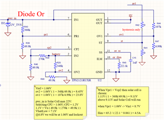
Could someone at TI please give me a sanity check on the resistor values I have chosen for my design (Solar Cell on Primary (IN1), 2S Li-Ion on Secondary (IN2)).  

My thought is using XVREF until I fall below this then the internal VRef 1.06V will take over and create an UV lockout.  I want to use high values to protect current wasting.

Thank you

Steve
  • Hi Steve,

    Please see previous responses about resistor values. One thing I would like to note is that if both PR1 and CP2 are below VREF, and both INx are above the UV threshold (2.8V) and below the programmed OV threshold, the device will go into VCOMP mode and output whichever input is at a higher voltage rather than create an UV lockout/disable.

    Also, you can further reduce quiescent current by combining the PR1 and OV1/CP2 and OV2 resistor dividers, so that for each input you have one resistor channel rather than two, please see channel one of the below picture.

    Also, please DNP R42/R41. If you will use a resistor between ST and PR1 for hysteresis, DNP R41 and put a nonzero valued resistor in R42, and if you will not be using ST at all, then DNP R42 - leaving ST floating or pulling it to GND is fine. Having both R42 and R41 as jumpers will just constantly lower the PR1 voltage.

    Thanks,

    Patrick

  • Thanks Patrick!  Yes I have R41/R42 in my variants and did not show it on my snapshot.  Also you supported what I already imagined wrt VCOMP mode and I am anticipating that as I built the XVREF right above 1.1V the internal Vref.....

    Thanks for the help.

    Steve