This thread has been locked.

If you have a related question, please click the "Ask a related question" button in the top right corner. The newly created question will be automatically linked to this question.

BQ25792: Some technical question

Part Number: BQ25792
Other Parts Discussed in Thread: TPS25855-Q1, BQ25798

Hi Team,

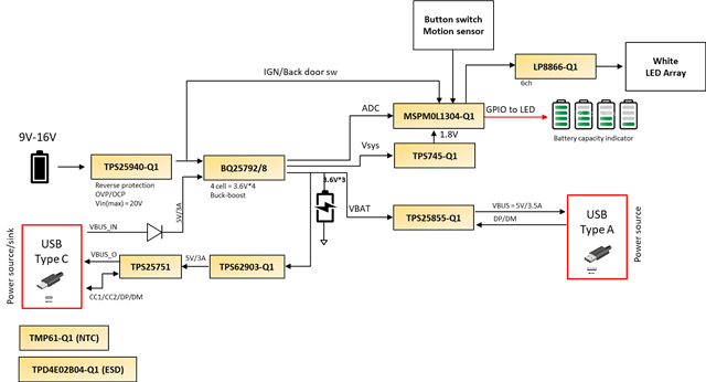
  • Q1 : If we don’t need to use DP/DM into BQ25792, how could we shut down the DP/DM or can we leave it floating or short to GND?
  • Q2 : We want to use external NTC to control charge current via I2C, is it feasible? How to do it?
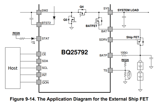
Ship mode :

To extend battery life and minimize the system power loss when system is powered off during idle, shipping or storage, the device can turn off BATFET and external ship FET to minimize the battery leakage current. The ship mode is enabled when the host sets SDRV_CTRL[1:0] to 10. The I2C is still enabled, but the charger system clock slows down to minimize the device quiescent current.

  • Q3 : If Ship FET turn off which means that the battery can’t provide the power to MCU, how can we disable the MCU. Do we need to feed Vbus to BQ25792 and let BQ25792 disable the ship mode?

Regards,

Roy

  • Hi Roy,

    Our experts are on holiday break. They will respond to you when they return.

    Best Regards.

  • Hi Roy,

    Regarding Q1, you can leave DP/DM floating to allow the highest IINDPM setting unless it is clamped by ILIM_HIZ resistor divider.

    Regarding Q2, if the charger TS pin is connected to NTC, the charger automatically limits charge current or reduces charge term voltage based the settings in registers 0x17-0x18.

    Regarding Q3, no. The charger's I2C is powered from BATP pin, which is always connected to the battery pack.  The charger has a built in 10s delay after the MCU tells the charger to turn off the shipFET. 

    Regards,

    Jeff

  • Hi Jeff,

    Thank you for your comments.

    For #2, can I use fixed resistor to TS pin and dynamically adjust the 0x17-0x18 register to change charge configuration via I2C. In short, we want to manually change the charge config instead of using TS pin.

    Regards,

    Roy

  • Hi Roy,

    The TS pin is expecting a voltage that varies with battery temperature. V(TS)~=0.5xV(REGN) corresponds to T(thermistor)=25C.  Then REG0x17-0x18 auto changes the charge current and/or temp based on V(TS) changing.  I do not see how having a fixed TS voltage will work because the register options are quite wide.  However, if you have a fixed TS pin voltage that works for your application, I see no reason why it would not work.  Or if your application has a DAC that can modify V(TS), that would work best.

    Regards,

    Jeff 

  • Hi Jeff,

    Actually, we don't want to use TS function. We want to manually adjust the 0x17/0x18 by using I2C bus.

    Roy

  • Hi Roy,

    REG0x17/0x18 only affect voltage and current if TS is used.

    Regards,

    Jeff

  • Hi Jeff,

    It looks like that the 0x17and 0x18 register working if we used the TS pin function.

    Can we give the TS pin a fixed voltage and then adjust the REG01/REG03 by using our MCU.

    Our purpose is that we don't want to use TS function and we would like to use our temperature sensor ADC value to adjust the charge current and charge voltage.

    Regards,

    Roy

  • Hi Roy,

    If you can find a fixed voltage that works for your application, I see no issue.

    Regards,

    Jeff

  • Hi Jeff,

    Thank you. May you share the common use case that customer enable/disable ship mode? 

    One idea from me is that pull high QON(bar) pin to VBAT. (enable ship mode). 

    When 12V vsys into BQ25792 and then use MCU send low signal to QON(bar) to disable ship mode. 

    How do you think?

    Roy

  • Hi Roy,

     An I2C write is to SDRV CNTRL register is required to enter ship mode after VBUS is removed. /QON is internally pulled high and can be pulled low to exit ship mode. 

    Regards,

    Jeff

  • Hi Jeff,

    I see there is DP/DM on the BQ25792. Can we use DP/DM to change the BQ25798 register to disable ship mode? Our scenario is that BQ25792 ship mode is default enabled. And we want to use type A connector to disable the ship mode. But I'm not sure how can we connect TPS25855-Q1 DP/DM and BQ25792 DP/DM together. Do you have any idea?

    Regards,

    Roy

  • Hi Roy,

    No.  Charger's DP/DM is only used to detect input current limit of the legacy USB BC1.2 ports and some HVDCP adapters during the first 2 seconds after power attach.  So charger and TPS DP/DM lines can be connected together as long as the TPS part does not access the DP/DM for the first 2 second after up.  Or charger DP/DM can be left floating and ILIM_HIZ can set input current limit register clamp until host is up to change the input current limit register.  Either /QON press and hold or host I2C write or power attach is required to exit ship mode.

    Regards,

    Jeff 

  • Hi Jeff,

    Thank you for your help.

    In addition, can we use BQ25792 DP/DM/VSYS as type A charging port?


    Regards,

    Roy

  • Hi  Roy,

    I do not recommend this.  VSYS regulation isn't tight enough to meet USB spec.  Also, the DP/DM is only designed to auto read power source input current limit at power up.  

    Regards,

    Jeff

  • Hi Jeff,

    Either /QON press and hold or host I2C write or power attach is required to exit ship mode.

    But in ship mode, the MCU(host I2C) doesn't have power and so there is no socket to do the action. Or do you recommend to let battery connect to MCU all the time?

    Do you have any other customer method that  how can they achieve the action?


    Regards,

    Roy

  • Hi Roy,

    If no MCU then /QON press and hold or input power attach are the only ways to exit ship mode.

    Regards,

    Jeff

  • Hi Jeff,

    May you help check the schematic for me? This is my first time to design the power bank EE, may you help check more detailed for me? Thank you.

    1. Is it correct of the MOSFET for ship mode? BAT_P is positive of battery.
    2. Is it possible to simplify the input side MOSFET?
    3. Our charge current would like to set 1A. Is the resistor and mode setting correct?
    4. For charge voltage, is it defined by I2C? We would like set it as 12.6V
    5. We plan to set TS as fixed resistor, we would like to dynamically control the battery charge current/voltage by our MCU instead of battery charger, is it ok?

    Regards,

    Roy

  • Hi Roy,

    On the schematic, C35 must be connected to REGN not TS.  Also, C34 on SDRV is not needed/recommended.

    Regarding 1, yes.

    Regarding 2, if there is the possibility of both inputs being connected at the same time, no.

    Regarding 3, yes. PROG pin resistor = 10.5k sets default BATREG=12.6V and ICHG=1A.

    Regarding 4, see 3 above.

    Regarding 5, yes.  You can use to equal resistors for the TS pin divider if you want to disable it.

    Regards,

    Jeff