This thread has been locked.

If you have a related question, please click the "Ask a related question" button in the top right corner. The newly created question will be automatically linked to this question.

LM5155: SS pin biasing effect on other pins

Part Number: LM5155
Other Parts Discussed in Thread: LM3478,

Hi Niklas,

I have a couple of questions, I am going for a 4.7uf cap on SS pin to get a soft start of 500msec. 

  • Is there any max capacitance limit on SS pin ?
  • Will this affect the RT pin bias resistor value or COMP pin network ?
  • What is the value of fRT (typical) ?
  • Would it be better to go with the high switching frequency with 500msec of soft start ?

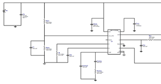
Attached is the snap of Webench design that I have currently.

Please let me know.

Thanks..!!!

  • Hi Ishan,

    I think it is not necessary to have 500ms soft start time.

    What is the input voltage, output voltage and load current?

    Best Regards,

    Feng Ji

  • Hi Feng,

    The nominal input voltage would be 24VDC and required output is also 24VDC. But there will be situations where the voltage can fluctuate from 18-32VDC. 

    The load is two solenoid valves, one rated at 24VDC-250mA and other at 24VDC-30mA. These loads will come in picture as and when required.

    Due to inductive loads, I have added a 100uF electrolytic capacitor at the output. Our end product has an inrush limit of 350mA, the 24VDC input power supply is selected accordingly.

    Thanks..!!!

  • Hi Ishan,

    Please keep in mind that the voltage at the input will pass to the output directly for the boost. That means you will get 31.5V output when the input is 32V.

    Also, you cannot reduce the inrush current before the output reaches the input voltage.

    Do you have the waveform of the inrush current?

    Best Regards,

    Feng Ji

  • Hi Feng Ji,

    As of now I am using LM3478 in sepic mode and facing and inrush current (2.2A) issue. I was suggested to use LM5155 instead to resolve the inrush current issue. But as you told that output would be 31.5V in case of 32VDC input, are you sure if this is the case in Sepic mode ?

    Please let me know.

    Thanks..!!!

  • Hi Ishan,

    Thanks for the update.
    You are correct that this application is possible for a SEPIC implementation.
    The topology was not visible just from the schematic picture, so Feng assumed it is a boost topology.

    In SEPIC, the output voltage can be lower than VIN and the inrush current can be limited with the softstart, as input and output are not directly connected.

    To go back to your original questions:

    • Is there any max capacitance limit on SS pin ?
      No, there is no max limit given by design, but very long softstart times are not recommended, as the design regulates in open loop during the softstart period
    • Will this affect the RT pin bias resistor value or COMP pin network ?
      The switching frequency is not affected.
      The comp pin network only becomes relevant when the softstart is finished. During softstart, the device compares the FB voltage to the rising reference at the SS pin. This means to the output voltage will rise slowly until it reaches the designated Vout level. The larger the SS cap, the slower the ramp of the SS pin reference.
    • What is the value of fRT (typical) ?
      For a SEPIC design, common fsw are in the range from 100kHz to 500kHz. There are also designs that run with 2MHz, but this can result in high switching losses und thermal heat-up of the board.
    • Would it be better to go with the high switching frequency with 500msec of soft start ?
      It is recommend to select the fsw based on the inductor specs and design goals for regulation speed & efficiency. The softstart has a minor role here.

    In general, it is recommend to choose a softstart time that is long enough for all output caps to be fully charged and then switches to normal operation mode directly afterwards.
    For fsw selection, I recommend using our quickstart calculation tool:
    https://www.ti.com/tool/download/SNVR481

    Please let me know if there are additional questions.

    Best regards,
    Niklas

  • Hi Niklas,

    Thanks for the detailed response, I appreciate it..!!!

    Based on your inputs, the finalized schematic at my end looks pretty much okay. I just have two doubts now.

    • The Webench Design doesn't show if I need to short AGND and PGND on PCB. But if I see datasheet for layout guidelines, it shows AGND and PGND shorted via EP. Please let me know if I need to do same.
    • The webench design has selected switching frequency of 2.2MHz, but as you suggested above that for SEPIC the switching frequency should be in range of 100-500khz. Would you recommend changing RT for KHZ range instead of MHz ? Please note that the load connected to LM5155 are two solenoids running at 200ma and 50 ma.

    Please let me know.

    Regards,
    Ishan

  • Hi Ishan,

    I am glad to hear you are making progress with your design.

    - Yes, I can AGND and PGND should be connected through a small trace or nettie. If there is no connection, the two ground levels can shift apart, which can result in instability or false signal sensing.
    The reference designs do the connection via the EP, which is most convenient from layout perspective.
    - The fsw range of 100-500kHz was a recommendation based on other SEPIC design I have seen. With output currents of 250mA, the power ratings are comparably low and there is much lower risk of thermal problems and high power dissipation. Because of this, a 2.2MHz design is fully valid and should work without problems.
    Our EVM design for LM5155 operates on 2.2MHz as well, so feel free to use this design for another reference.
    https://www.ti.com/tool/LM5155EVM-SEPIC

    Best regards,
    Niklas