This thread has been locked.

If you have a related question, please click the "Ask a related question" button in the top right corner. The newly created question will be automatically linked to this question.

TPS65988: FTDI Error

Part Number: TPS65988

Hello experts, Happy New Year, I have look in the forum but couldn't find the same situation:

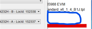
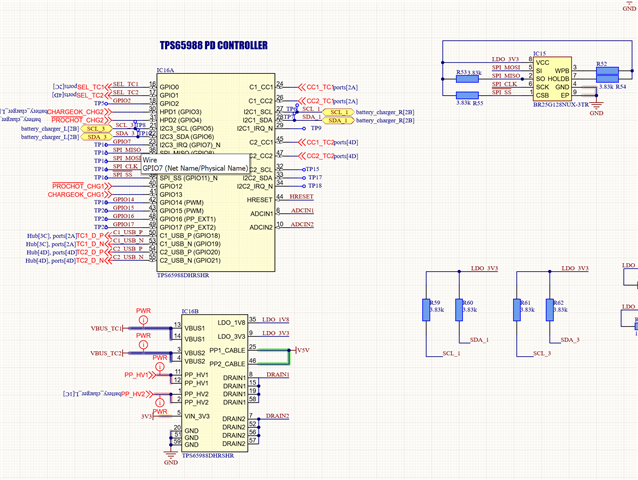
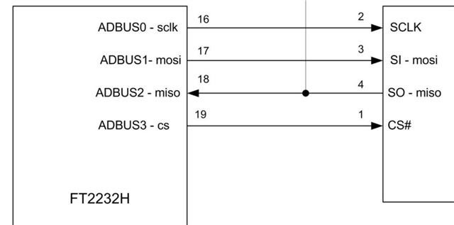
I have a custom board for the TPS65988, I am using a SPI memory and a FTDI FT232HQ adapter with the intention to program the flash memory.

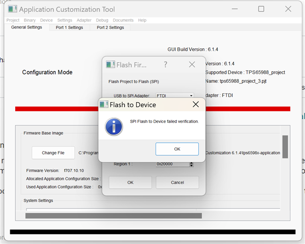
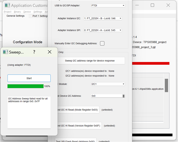
But when I try I receive the error:

Exception Encountered during SPI Flash to Device:*** ERROR in FTDI call (I2C_OpenChannel), status: 1

<type 'exceptions.Exception'>

Detail:

Traceback (most recent call last):

File "dialogWindow.pyc", line 5073, in flash_device

File "hw_interface.pyc", line 186, in hw_open

Exception

I don't know if is an error resulting of a wrong connection of the SPI or a conflict between the Flash, TPS and the FTDI. If you could give me some orientation I would be glad.

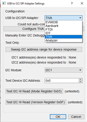
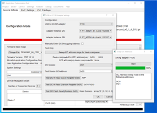
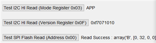
The program I am using to send the data to the flash is the Application Customization Tool.

Regards

Tomas

  • Hi,

    Can you check the adapter setting in the GUI?

    Regards

  • Hello Tommy, yes I can see the settings, it is placed in FTDI. 

    regards

  • Hi,

    I did not see this issue when using the FTDI that come with EVM.

    Are you trying to program the SPI flash with your FTDI adapter?

    Regards

  • hello Tommy, yes as I said I am trying to program the SPI flash with a FTDI adapter.

    The memory I am using is the BR25G128NUX-3TR. I can understand you don't see any issues with the FTDI that comes with the EVM since it is intendent to be use for that propose.

     Do you have any insight from the shown error? what they mean? 

    Exception Encountered during SPI Flash to Device:*** ERROR in FTDI call (I2C_OpenChannel), status: 1

    <type 'exceptions.Exception'>

    Detail:

    Traceback (most recent call last):

    File "dialogWindow.pyc", line 5073, in flash_device

    File "hw_interface.pyc", line 186, in hw_open

    If I can identify the origin of the problem might be able to correct it. I have done a test using a second board this time just with the Memory connected without the TPS and providing the 3.3V from the FTDI adapter, nevertheless the error persisted the same.


    By the way in my SW tool these registers can't be seen like this, and when I press in test SPI it also gives me an error. 


    Also in the area in blue of my SW tool the SW has a line that says "SPI and I2C adapter: TIVA"

    I hope this information can help you to give me some insights about the issue I am facing.

    Rgards

    Tomas

  • Hi

    Can you show me your FTDI connection to TPS65988 and the SPI flash?

    Since I am not an expert on FTDI I can only provide limited help here. Let's try to have your FTDI adapter connection the same as the EVM first.

    Regards


  • This is the sch, as you can see the memory is connected to the TPS65988 and to the TPx pads, in those pads I have connected the FTDI following the next connection:


    The EVM has some switches and jumpers that was difficult to realize how are they placed to perform the FTDI programming.

    Regards

    Tomas

  • Hi,

    Connection looks ok.

    Can you check if you are using the correct FTDI driver? From the error message this is most likely a driver issue.

    Regards

  • I have re-install all the drivers and software, but keep receiving the same errors. I wanted to ask:

    1) If the I2C shall be connected through the FTDI too for the programming tool software to work properly (As in the EVM schematic)? 

    2) Do I need to flash any specific FW to the FTDI IC itself to be able to work properly with the TI programming tool? 

    I have verified the power of the PCB and both EEPROM and TPS are powered up correctly. 

    Regards

  • Hi,

    Yes you need to have I2C line from FTDI connected as in EVM.

    Usually the FTDI driver that came with the GUI is the one that worked with the FTDI on EVM. I do not know which driver is needed for FTDI adapter.

    If you have an TPS65988EVM maybe you can try removing the booster pack portion and use that to program other custom board.

    Have you considered using a different flashing tool that directly flash the EEPROM/SPI Flash?

    Regards

  • Hi, 

    Ok I will try to use a FTDI adapter with both SPI and I2C, at the moment only have one with one channel. 

    I don't have available an EVM, but my question is not related to the driver but to the program of the FTDI chip itself, they can have different configurations (Firmware), do you have any information of which is used for the FTDI in the EVM ? is it MPSSE the default configuration it uses?

    I will check also the option for a EEPROM flash tool, at the beginning I thought that's how the TI's tool was working but if is using also the I2C channel then it is different.

    Regards. 

  • Hi Tommy,

    I have used the new tool with SPI and !2C channel and have some movement forward it is just giving me this error now:

    What this situation can tell me?

    The voltage in the pin 3.3V is stable and the device is connected to both USB power and battery.

    The FTDI is connected as in the EVM:

  • Hi

    Can you check if the I2C connection between FTDI and TPS65988 have 3.3V pull up?

    Not sure if there is a ground pin on the FTDI adaptor but you will want to connect the ground pin also.

    Regards 

  • I have tested several times, I have the pull up resistors, even changed the values to try, but the error in verification persist. I will try with a direct flashing tool.

    Mean while would like to ask if the "Read Success" has any special meaning ('B', [189, 248, 181, 158]). 

    Do you have any other suggestions? 

  • Hi,

    The read success is just checking that I2C communication is successful or not with TPS65988. Depends on the option you click, it report back the 0x03 or 0x0F register content.

    Regards

  • But it is in the SPI flash read test: 

    What does numbers say, in one of the standard configurations what will be the expected array?

    Again any suggestion in how to tackle these problems?

  • Hi,

    My apologies I didn't notice this is about the SPI flash read. 

    It is just a read back of a section of the SPI flash memory.

    I think the issue you encounter is due to the difference in the FTDI chip/FW we used on EVM and the FTDI chip on your adapter. It is most likely that the driver that came with the GUI does not support your adaptor's FW

    The FTDI driver that came with the GUI only works with the FTDI chip that came with the EVM and that driver only work with the specific FTDI FW version on the EVM.

    Regards

  • Hi  Tommy,

    In this case I would like to get your best advice to redesign the board and what adapter can I use for mass production, I can't use the eval boards tiva nor ftdi that comes with it for such task.

    Up to now I haven't been able to use the custom board in anyway. I am planning to produce a new prototype in order to be able to test it properly but definitely the programing is big challenge at this point.

    I have try to directly program the memory but that also didn't work, I have try Flash-Center tool among others but the memory I am using is not listed so I guess that's the issue with those tools.

    If I use a generic board that implement the FT4232HL  do you think the programming and debugging software will be able to work properly? What is it the FW that comes with the EVM?

    The FTDI driver that came with the GUI only works with the FTDI chip that came with the EVM and that driver only work with the specific FTDI FW version on the EVM.
  • Hi,

    In terms of programming and debugging I would recommend using Aardvark as from our experience this is more stable than using FTDI.

    What SPI flash you are using? From our experience you don't need to use the exact same IC name in the list as long as the SPI flash is similar enough.

    Regards

  • Hi Tommy, 

    Could you be more explicative this kind of pills answer make the process very difficult to go forward at good speed. 
     - Isn't Aardvark just a type of connector?
     - the memory is BR25G128NUX-3TR.

    My main issue as you can see in the whole thread is programing the memory to be able to even be able to use the TPS chip. 

    Could you give a longer time to answer my questions in the previous message and this please, I am really needing help and orientation with this project, the information about the operation of this chip is too scattered and confusing. 

  • Hi,

    My apologies, the Aardvark I am referring to is the Total Phase Aardvark I2C/SPI Host Adapter (https://www.totalphase.com/products/aardvark-i2cspi/). Using Aardvark you not only can flash the SPI flash directly from Total Phase Flash center but you can also use this as an I2C debug tool with the GUI.

    You can either create your custom part or use an other parts that have the same parameters, here a guide on how to create your custom part (https://www.totalphase.com/solutions/apps/how-to-create-add-custom-flash-part-to-flash-center-software/)

    Another option of programming the SPI flash is to use DediProg (https://www.dediprog.com/category/spi-nor-flash-device-programmer) but this can only flash the SPI flash (cannot interface with GUI for debug)

    These are the two options I recommend using to flash the SPI flash. 

    Using the FTDI chip to perform flash was unstable as we write the configuration to SPI through TPS65988 then verify the flash through TPS65988 hence why we moved away from FTDI. The above two options directly program SPI flash but with Aardvark it also offers the ability to interface with GUI and debug hence why I recommend using Aardvark.

    Regards