This thread has been locked.

If you have a related question, please click the "Ask a related question" button in the top right corner. The newly created question will be automatically linked to this question.

TPS65218D0: Connection between PMIC TPS65218D0 and MPU AM4378

Part Number: TPS65218D0
Other Parts Discussed in Thread: AM4378, , TPS65216

Hi,

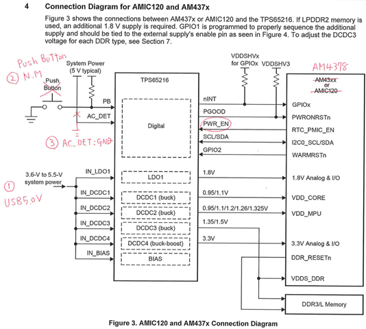
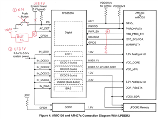
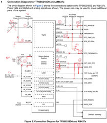
Is there any problem with the connection below between PMIC TPS65218D0 and MPU AM4378?

 [conditions]
・System Power USB5V
・No backup circuit is used
*Although the RTC timer is used, it does not operate in RTC-only mode.
- Do not attach a push button to the PMIC's PB terminal.

[PMIC:TPS65218D0]
①PB →5V pull-up
②AC_DET→GND connection
③CC→GND, IN_BU→GND connection
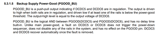
④PGGOOD_BU→OPEN
⑤DCDC5 (L5, FB5) → GND connection
⑥DCDC6 (L6, FB6) → GND connection
⑦nWAKEUP→OPEN
⑧PWR_EN → 5V pull-up (do not connect with MPU)

[MPU:AM4378]
⑨RTC_WAKEUP→GND
⑩RTC_PWRONRSTn→Input the signal converted from PMIC's PGOOD to 1.8V
⑪Connect CAP_VDD_RTC→VDD_CORE
⑫Connect VDDS_RTC→1.8V
⑬RTC_PMIC_EN→OPEN (Do not connect with PMIC)

I'm especially concerned about whether ② and ⑧ are correct.

Thanks,

Conor

  • Hi Conor,

    AC_DET pin needs to be tied to IN_BIAS source when not used.

    It looks like PWR_EN is the trigger for power up since AC_DET and PB inputs should be pulled HIGH at all times, so there should be no issue here. To enter full OFF state you will need to be able to shut off PWR_EN source (unless you plan to power off the main supply entirely which would shut down the part fully anyway).

    Double check your new power sequence against the original setup to make sure that you aren't violating any timing requirements from the AM4378.

    If you are not planning to use DCDC5 or DCDC6, it is recommended to set STROBE1 and STROBE2 to 0x00 in their respective register controls. However, according to the below clause from the datasheet it doesn't look like faults on DCDC5 or DCDC6 will cause a shut down sequence, so you should be able to leave these rails unsupplied.

    The TPS65216 is the same silicon as the TPS65218D0 but it excludes the Back-up systems (DCDC5 and DCDC6, CC, and IN_BU block). You may want to consider using this part instead if you aren't going to use the BU systems anyway.

    Powering AMIC110, AMIC120, AM335x, and AM437x with TPS65216

    Regards,

    James

  • Hi James,

    From your advice, I am planning to change to TPS65218D0 → TPS65216.

    [PMIC IC connection]
    ①System power→USB+5V
    ②PB → +5V pull-up (push button not implemented)
    ③AC_DET→GND

    [Question]
    Is there any problem with the above connection? Also, if I power down the PMIC by setting PWR_EN to low, will it start working again because AC_DET is always low?

    Thanks,

    Conor

  • Hi Conor,

    If you want to control the device power up with PWR_EN only, I would recommend connecting AC_DET to your 5V source in the same way as the PB pin. Looking at the device state tree from the datasheet (shown below), one of the conditions for the PMIC to move to OFF state from PWR_EN low trigger is for AC_DET to be pulled high.

    Regards,

    James

  • Hi James,

    Thank you for your reply. We have revised the circuit diagram based on your answer, so could you please check it again?

    [Connection]
    ①SYSTEM POWER: USB bus power 5V
    ②PB: Not mounted (5V pull-up)
    ③AC_DET: Reset IC connection
     *AC_DET is LOW level for a certain period of time when the power is turned on → 5V (uses delay function of reset IC)
    ④PWR EN: Pull down

    Is it possible to achieve the following with the above configuration?
    ・Start without PB
    ・Shutdown using PWR_EN
    ・After shutting down, the USB cable must be unplugged and reconnected or it will not work.

    Thanks,

    Conor

  • Hi Conor,

    James should be able to take a look and respond on Tuesday (Monday is a holiday for us). I apologize for the delay.

    Best regards,

    Matt

  • Understood. We look forward to hearing from you.

  • Hi Conor,

    The configuration you shared should work as you described, although you may want to add a resistor to GND on the AC pin just to make sure the pin doesn't float between GND and some high voltage.

    When you plug in main power to IN_BIAS when AC_DET is low, the PMIC will start the power up sequence and wait for 20s to see PWR_EN pull HIGH.

    After PWR_EN is pulled HIGH and the device has reached active state, pulling PWR_EN to LOW will cause the part to return to OFF state as long as all rails are tied to a sequence slot (STROBEx).

    If you don't have a way to toggle PWR_EN after the shutdown, you would need to toggle AC_DET by unplugging and reconnecting the USB cable as you mentioned.

    Regards,

    James

  • Hi James,

    The configuration you shared should work as you described, although you may want to add a resistor to GND on the AC pin just to make sure the pin doesn't float between GND and some high voltage.

    As shown in the image I sent earlier, the AC_DET pin is connected to the reset IC.

    Does it mean that what I am doing is to put a pull-down resistor between the reset IC output and the AC_DET pin?

    Thanks,

  • Hi Conor,

    That's what I was thinking but it may not be necessary to have the pull-down resistor. It's just a suggestion to consider. I sometimes see the pull-down resistor on pins that need to discharge to GND in a timely manner.

    You can leave out the resistor suggestion if that's easier right now.

    Regards,

    James

  • Hi James,

    OK, I understand your answer.

    Thanks,