This thread has been locked.

If you have a related question, please click the "Ask a related question" button in the top right corner. The newly created question will be automatically linked to this question.

LM7481-Q1: Designing Controller and circuitry for hot-swapping

Part Number: LM7481-Q1
Other Parts Discussed in Thread: LM7481

Hello, we are planning to use the LM7481 on an interface that could be hot-plugged by a live voltage source. Given this we need to mitigate the inrush due to input capacitance.

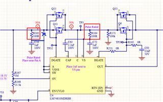
We would like to use 100ohm resistors in series with the capacitance that is connected to Pin 2 (A), Pin 11 (CAP), and Pin 10 (VS), to limit inrush as without them it would be several amps into the capacitor.

Is there an issue with having a 100ohm series resistor (R164) in line to the CAP and VS pins as shown in the below schematic?
Would there be an issue if we have a 100ohm (R163) in line with the Anode connection? (if we were to modify circuit with blue connections shown below) My concern was pins A and C are used for accurate reverse current protection, so additional resistance might affect the accuracy of that protection depending on how that stage is designed internal to the chip?

Thank you,

Peter Davis


  • Hi Peter,

    You can reduce C72 to 100nF and R164 to 10 ohms. A 100nF across VS to GND should be sufficient to provide decoupling for the IC internal power rails.

     C36 is not required unless you have a noisy power supply. As you mentioned R163 can cause shift in Rev and Reg thresholds due to the current flowing into A pin through R163. So, unless the power supply  is noisy, you can consider shorting R136 and removing C36. 

  • Hi Praveen,

    Thanks for responding,

    I selected 1uF, due to the DC derating. Our bus voltage will be 50V, so the derating of our capacitor puts effective capacitance around 0.2uF. When you recommending a 100nF cap, are you assuming this value after dc derating? I'd prefer to keep the 100Ohm to limit inrush current. Is there any issue with having the higher value? Based on the charge pump circuit, worst-case we would expect 3.8mA during the capacitor refresh in addition to the Vs quiescent current, which the resistor should be able to handle. Am I missing anything in my assumptions?

    Thank you for the clarification, our supply should be relatively clean, I will leave as is for testing.

    Regards,

    Peter 

  • Hi Peter,

    • The RC on the VS pin slows down the voltage ramp up on VS pin to reach VS_PORR because of which there can be additional delay during startup.
    • The 100 ohms in series to the VS pin can be problem when operating at low voltages lower than 5V where the quiescent current is high. If your operating is at 50V, then there should not be any issue but we would recommend you to test the circuit under all operating conditions. 
    • 100nF decoupling is fine as long as the  de-rating of cap is less than 30%. In your case the de-rating looks to be around 80%. In this case you can consider using higher cap value.