This thread has been locked.

If you have a related question, please click the "Ask a related question" button in the top right corner. The newly created question will be automatically linked to this question.

LM51571-Q1: LM51571-Q1 technical support inquiry

Part Number: LM51571-Q1
Other Parts Discussed in Thread: LM5157, LM5155

Hi

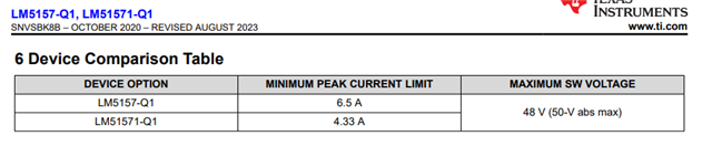
I have an inquiry about LM51571-Q1.

Currently, we plan to receive 12V DC and raise the voltage to 48V to supply Power Amp Drain.

1. The loaded PA current is 2A@48V.
The efficiency graph in the datasheet does not show 2A.
I would like to inquire whether it can be used at 2A and the efficiency is over 90% when the Vsupply is 12V.

2. The datasheet states that Maximum switch current is limited by pre-programmed peak current limit (ILIM), and is guaranteed when TJ < TTSD.
What is TTSD?

3.The switching frequency needs to be adjusted. To use it in a Power Amp, should I set it as high as possible and adjust the resistance value, or should I adjust it to an appropriate value?

4. Will there be any problems using LM51571-Q1 as a communication AMP?
And are there any characteristics that are more important to consider when it comes to power converters?

5. Is there a product more suitable than LM51571-Q1 in the above specifications?

Qucell Networks outsources the production of its products to a Chinese company called CIG, and CIG directly purchases TI products.

That's why it's difficult for my company to get technical support for TI products.

For this reason, we have contacted you directly through our website.

We would appreciate it if you could let us know after checking your inquiry.

Thank you and Happy New Year

  • Hi Hyuntae,

    Thanks for using the e2e forum.

    1.) & 2.)
    LM5157(1) has the following max current values given by the datasheet:

    For a worst case situation of min Vin and max load, there can be peak inductor currents up to 9A.
    This calculates from the average inductor current + the switching current ripple. This peak inductor current needs to be below the current limit of the device.
    Therefore, this device is not fit for the application. You could switch to the LM5155 device, which uses an external FET instead and does not have this current limitation.
    For quick calculations on the peak currents, you can use our Power Stage Designer tool:
    https://www.ti.com/tool/POWERSTAGE-DESIGNER

    3.) & 4.)
    The selected switching frequency strongly depends on the application and the highest possible fsw is not always the best implementation.
    Higher fsw will allow a smaller inductor and faster compensation, but will increase switching losses that can reduce overall efficiency.
    We have a EVM design running at 440kHz which might be a good reference starting point
    https://www.ti.com/tool/LM5155EVM-BST
    On general boost topology design, we have a lot of additional resources online:
    https://www.ti.com/lit/an/snva824/snva824.pdf
    https://www.ti.com/download/trng/docs/seminar/Topic_3_Lynch.pdf

    5.)
    Yes, LM5155 should be suitable.
    You can also check the according quickstart calculation tool for initial calculations:
    https://www.ti.com/tool/download/SNVC224

    Best regards,
    Niklas

  • Hi Niklas
     
    Thank you for your quick reply.
    I have an inquiry as I am considering the LM5155 you recommended.
    The website states that the output can be stepped up to 300V.
    However, the datasheet states that the Output VCC of "8.1 Absolute Maximum Ratings" is -0.3~18V.
    Can this product step up to 50V?
    Please confirm.
    thank you
  • Hi Hyuntae,

    Thanks for the feedback.

    Yes, the device can step up to 50V output voltage.
    The voltage limits of each pin are given in the abs max rating.
    The VIN limit is affected by the BIAS pin, which allows a max voltage of 45V.
    When VCC is connected with a cap to GND, the VCC voltage will be generated internally (~7V). This voltage is not affected by VOUT.

    Please make sure that the forwarding diode and the output capacitors have a rating higher than 50V (+ some margin), to support the step up voltage.

    Best regards,
    Niklas

  • Hi Niklas

    Thank you for your reply

    Your answer helped me a lot.

    thank you