Hi!
We are unable to successfully use the TPS61022 - it always fails in our board.....and it is a bit of head-scratcher!!
The failure mode is that the SW pin is shorted to GND.
The part is configured for a 5.5V output and a single Li-Ion battery input (The part fails whether we use a battery or power supply as the input).
The schematic is as follows:
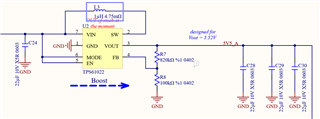
It might be a bit hard to see the values - the caps are 22uF, 10V, 0603 X7R ceramics.
The upper resistor R7 is 820K, 1%; The lower resistor is 100K 1%
There are (not shown) 2X 100uF, 16V aluminum polymer caps (24mOhm ESR) on VIN as well. (Digikey P16468CT-ND).
We tried 2 different inductors. Both are from the datasheet - The Wurth 744316100 and the Coilcraft XAL7030-102MEC. Same result.
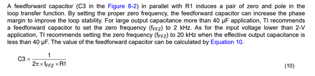
We didn't try a feed-forward cap on that board (I did on the eval board (5V) but it didn't seem to matter);
The circuit has to supply a maximum of 2.25A at 5.5V.
It has never failed at no load.
It always fails if we try to put the full load.
I had it supplying 100mA and then 200mA, seemingly fine (Using a pure resistor load and no other load).
Then a power on/off/on cycle...and the part was blown up. I can't recall if the 200mA load was connected during this cycle, but most likely it was.
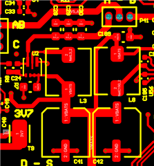
U2 is the device
C41, C42 are the electrolytics
L3 is the inductor
C24 is the input ceramic
C28, C29, C30 are the output ceramics.
Any insights.... clues.... suggestions? Schematic, layout???
Thanks in advance!
Jerry Molnar