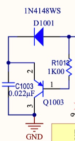
Hello,
I have a design with two LM5069 placed back-to-back to act as a bidirectional switch and both switches are closed during my tests. There is an AC/DC stabilized power supply (54V) on one side and a 10S-3P battery charger on the other side (Linear Tech. LTC4020). Signal OUT_SWITCH and EL_LEFT_MES were measured and are identical.
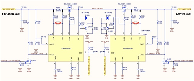
I believe both the charger and the AC/DC induce a bit of ripple on the power line.
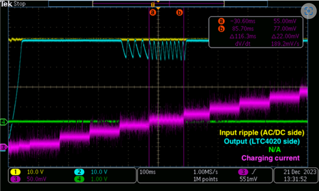
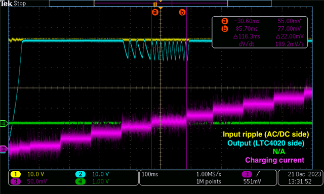
At specific charging current, the transistor of the LM5069 on the AC/DC side is acting linearly and overheats, leading to the transistor destruction and the output is oscillating (see below).
I checked the fault timer pin and it doesn’t rise, meaning this is not linked to the power limit or current limit.
I bypassed the OVLO protection and the problem persists and there is no UVLO protection in my design.
I checked the GATE pin. When acting normally, it is 12V above VIN as stated in the datasheet. When the output starts to oscillate, it drops to about 3V/4V above VIN (see below).
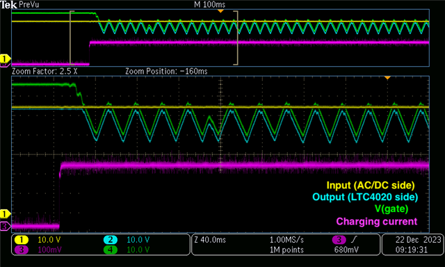
I added a capacitor between the transistor drain and ground and it improves the switch behavior without fully correcting it : the output doesn’t oscillate as much but V(gate) is still not stable for a while (see below).


Did you already encounter a similar issue with this component?
Any idea what could be the reason of the oscillations?
Thank you,
Best Regards.


