Other Parts Discussed in Thread: LM5180EVM-DUAL, LM25184, LM5180
My evaluation processing, Please take a look and help
1.Ordered the dual output evaluation board(LM5180EVM-DUAL) form TI via the following link. https://www.ti.com/tool/LM5180EVM-DUAL
2.Order the LM25184QNGURQ1 chip from TI too
3.Order the COILCRAFT: ZA9673-BED transformer from Digi key the datasheet can be found from the following link: ZA9670, ZA9671, ZA9672, ZA9673, ZA9674 Flyback Transformers (coilcraft.com)
4.By reference the LM5180-Q1 Dual-Output EVM User's Guide (Rev. B) (ti.com), we did the following:
- 1.Replace the LM5180 chip with LM25184 chip
- 2.Replace R6 from 154K to 121K
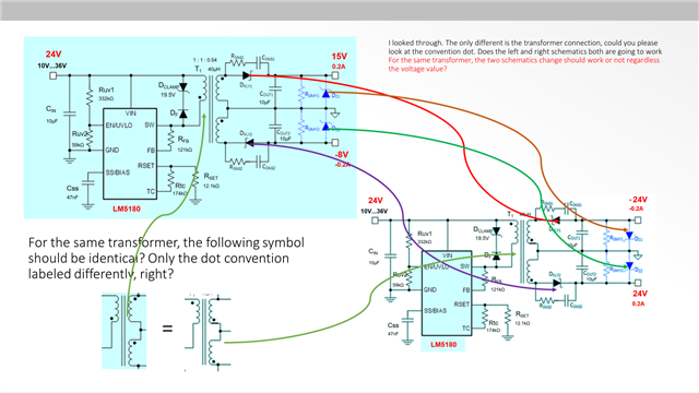
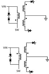
- 3.Replace transformer with ZA9673-BED, and short PIN-1/2 and PIN-3/4.
- 4.Replace both Zener D5 and D6 with 27 Volts
- 5.Change the polarity orientation of D1 and D3
- 6.Short C14
- 7.Apply 24V Voltage at the input
- 8.Take measurement of the output waveform with and without 1K resistor be connected between Vout1-GND and Vout2-GND.
5.Please see the test result
- 1.The first slide is open load condition, the out1 and out2 ripple are about Vpp = 50mV, and it consume about 500mW power.
- 2.The second slide is the test with 1k resistor between Vout1-GND and Vout2-GND, the current suppose to be only 24 mA for both Vout1 and Vout2, but the ripple is too much.
- 3.Any idea what is exactly going on here?
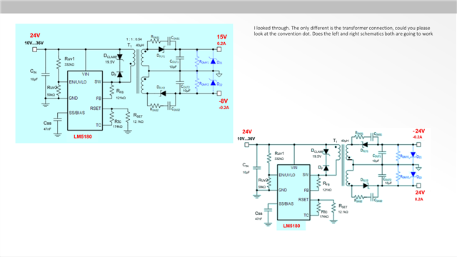
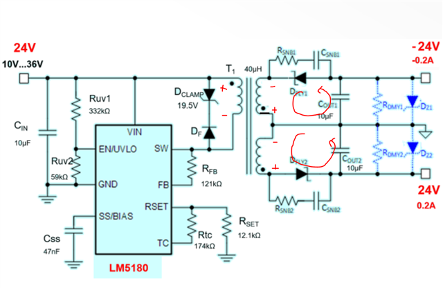
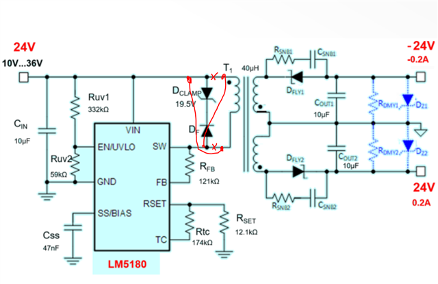
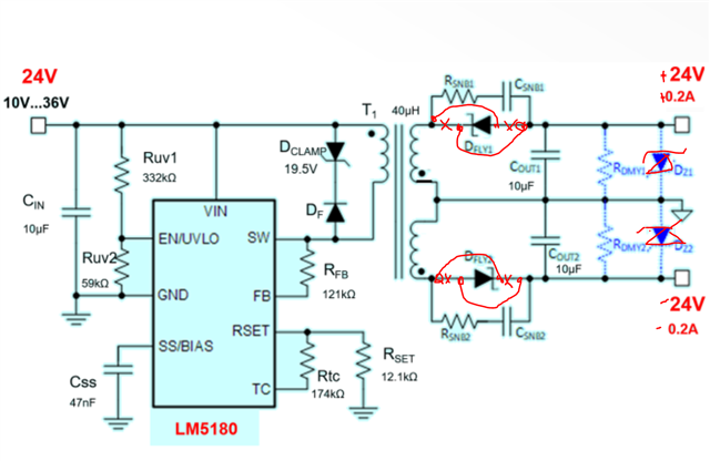
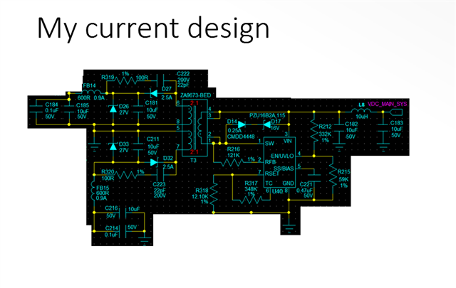
6.The schematics is what I am planning to implement on my design, the PCB layout is done, and I have put it on hold for fabrication. Because based on the evaluation result today, I am worried NOW! Please help ASAP, thank you!