Other Parts Discussed in Thread: MSP432E401Y, UNIFLASH
Question 1:
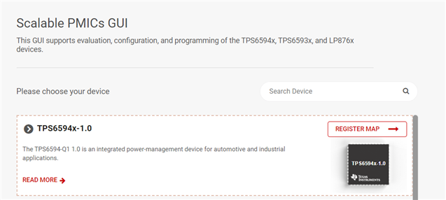
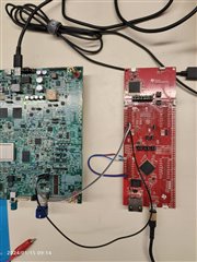
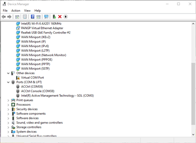
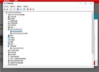
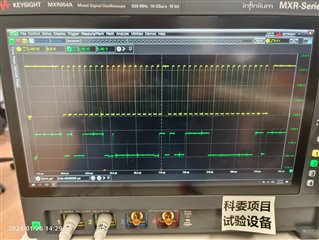
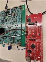
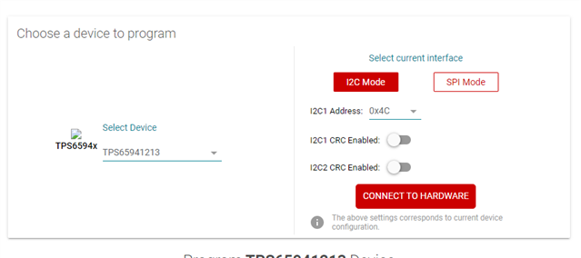
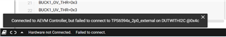
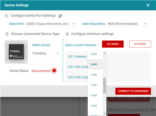
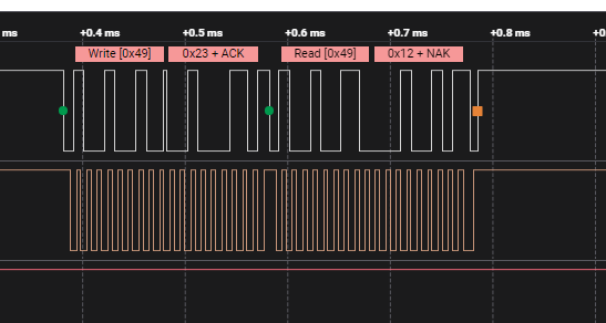
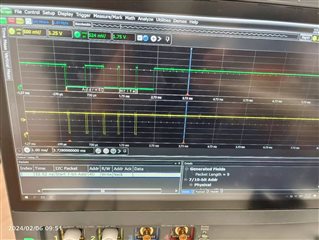
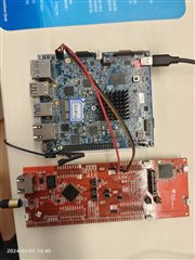
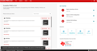
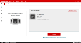
Through the debugging board of MSP432E401Y MCU Launchpad, the TPS6594 chip is connected through GUI. The output connection is unstable, sometimes good and sometimes bad, and the I2C pull-up resistor is 1.5K. It can connect to the MSP432 board, but cannot connect to the chip. The latest GUI version used is 4.0.
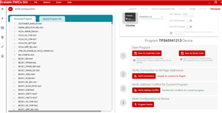
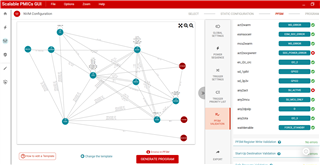
Question 2: In the GUI, when I loading the configuration template for J721E, two errors were found during PSFM verification, namely act2socpwerr and any2act.
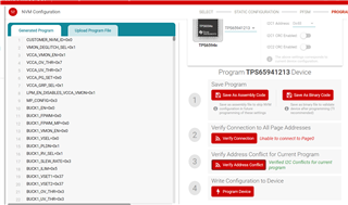
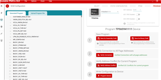
Question 3: Occasionally, after successfully connecting the TPS6594 chip, the quick start button automatically recognizes only one chip during device operation. The address of the chip is 0X4C. The other chip cannot automatically recognize.
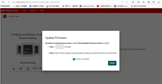
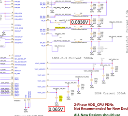
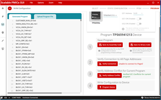
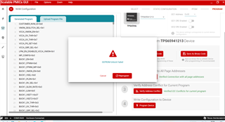
Question 4: After successfully connecting one chip, the template configuration of J721e was burned, and it could not be burned. A fault was reported that EPROOM unlock failed. A multimeter was used to test the actual output of the chip, but the actual voltage of the chip was not displayed, so NVM was not burned successfully.
Please help resolve the 4 issues as soon as possible , Thanks very much!