This thread has been locked.

If you have a related question, please click the "Ask a related question" button in the top right corner. The newly created question will be automatically linked to this question.

TPS6594-Q1: TPS6594-Q1 external components calculation formula request

Part Number: TPS6594-Q1

Hello sir,

I check the TPS6594-Q1 datasheet and app note and can't find TPS6594-Q1 BUCK and LDO related external components value calculation formula, including inductor value, input/output capacitors, output ripple. Could you provide related documents to calculate them? I know the datasheet has recommended typical value, but I also want to calculate them by formula to check if apply for our use case. I also want to check the BUCK's loop steady and transient response, how to calculate or validate them for TPS6594-Q1 BUCK? 

BTW, could you explain me the reason, in PDN_3F power solution, why TPS6594133A-Q1 switching frequency is set to 4.4MHz in default NVM, not 2.2MHz. I notice for PDN_0C power solution, TPS65941213 switching frequency is set to 2.2MHz in default NVM. Why for the same family TPS6594-Q1, different dedicated part number the switching frequency is different, what's your consideration? 

BR.

Cynthia

  • Another question,

    According to TI app note (SLVA477B), I calculate inductor value, but the value is much bigger than TI datasheet recommended value. For example,

    FSW=2.2MHz, single phase, VIN=3.3V, VOUT=1.8V, IOUT=0.352A, efficiency is 93% (from PMIC Efficiency Estimator Tool)

    calculate inductor value is 3.5uH in 30% ripple current ratio and 3.0uH in 35% ripple current ratio, but datasheet recommend value is 470nH for all use case. It makes me confused. Please give some advice.

  • BTW, could you explain me the reason, in PDN_3F power solution, why TPS6594133A-Q1 switching frequency is set to 4.4MHz in default NVM, not 2.2MHz. I notice for PDN_0C power solution, TPS65941213 switching frequency is set to 2.2MHz in default NVM. Why for the same family TPS6594-Q1, different dedicated part number the switching frequency is different, what's your consideration? 

    At 4.4MHz the minimum required output capacitance per phase is significantly lower. Thus reducing the BOM. At 2.2MHz switching frequency, 100uF per phase is needed. At 4.4MHz, 70uF per phase. For the PDN-3F, since most of the heavy loads are handled by the large external buck convertors. The focus was reduce the BOM for the lighter load rails.

  • calculate inductor value is 3.5uH in 30% ripple current ratio and 3.0uH in 35% ripple current ratio, but datasheet recommend value is 470nH for all use case. It makes me confused. Please give some advice.

    The TPS6594 data sheet has to account for the full current range of the rail. For most of the BUCKs the max DC current is 3.5A. If you use IOUT=3.5A into your equations, you get 0.35uH in 30% ripple current situation. Accounting for some inductors have tolerances of 20% and temperature impact on external components, 0.47uH makes sense. 

  • For our actual use case, every power rail load current would not use to full load up to 3.5A, according to our actual case, 

    for example, BUCK3 only used 0.3A, I think we should follow actual current load, does not follow BUCK max DC current to design, then to considering inductor tolerance, this inductor value will be bigger than 3.5uH. If follow max DC to calculate, the ripple will be much bigger, it's not good to our design.

    Please correct me if I understand is wrong, or maybe other aspects i can't consider, please let me know.

  • Hello Cynthia,

    Please correct me if I understand is wrong, or maybe other aspects i can't consider, please let me know.

    Your calculations are only factoring in the steady state situation. Increasing the inductor value by a factor of 10x will negatively impact the rails ability to achieve the desired rail rise times and fall times. This could lead to faults during power up. For example if a 1V rail has the slew rate set to 10mVus, then the voltage monitor for that rail will turn on ~300us after the enable signal for that rail is sent to that block. If a much larger inductor prevents the rail from achieving 10mV/us, it will might not hit 1V before the voltage monitor turns on. This would cause an undervoltage fault. 

  • These points are the only I missed to consider?  How to balance these impacts between ripple and rise/fall time?  I calculate inductor value based on TI document mentioned requirement which should meet 20%-40% ripple ratio (typical use 30% to evaluate), I think this point is right. For rise/fall time, how to calculate to check if also meet the requirement? Datasheet recommended inductor value also don't consider these two impacts, only considering full load current condition. Do you have any other evaluation calculation method that from TI experience which considering more fully?

    BTW, does 10x refer to typical value or TI recommended max value? where is from factor of 10x? Is TI experience value? Or have other formula to calculate? 

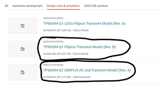
  • I mentioned "10x" because your hand calculations were taking you to 3.5uH, while the recommended value is 0.22uH. If you wish to deviated from the recommended solution there are simulation and design tools for the TPS6594 that can be used to judge transient and AC performance. However, I highly recommend sticking with the proven recommended solution. 

  • hello Michael,

    Simplis tool without free options to download in TI website?

  • Hello Cynthia,

    We don't have a free tool for simulating the transients. We just provide the models free to be used by those standard simulation tools.