This thread has been locked.

If you have a related question, please click the "Ask a related question" button in the top right corner. The newly created question will be automatically linked to this question.

TPS2121: Output power is interrupted when a second power input is connected to the MUX.

Part Number: TPS2121

Hello,

I have a design using the TPS2121 which I am using to seamlessly switch between two 12V inputs. The inputs are provided by 12V/3A output AC/DC power adapters. When one of the 12V adapters is connected to the MUX on either input I see a 12V output as expected. However, when I connect the second 12V adapter to the other input the 12V output drops, causing my board to reset as the downstream DC/DC regulators brown out.

The power adapters are identical and output ~12.2V in to an open circuit.

I have attached the schematic I am using here. Both 12V inputs have a TVS diode and a CM Choke (for EMI purposes) on the input path to the TPS2121. I believe I have the TPS2121 set up for XCOMP mode as per table 9-3 in the datasheet.

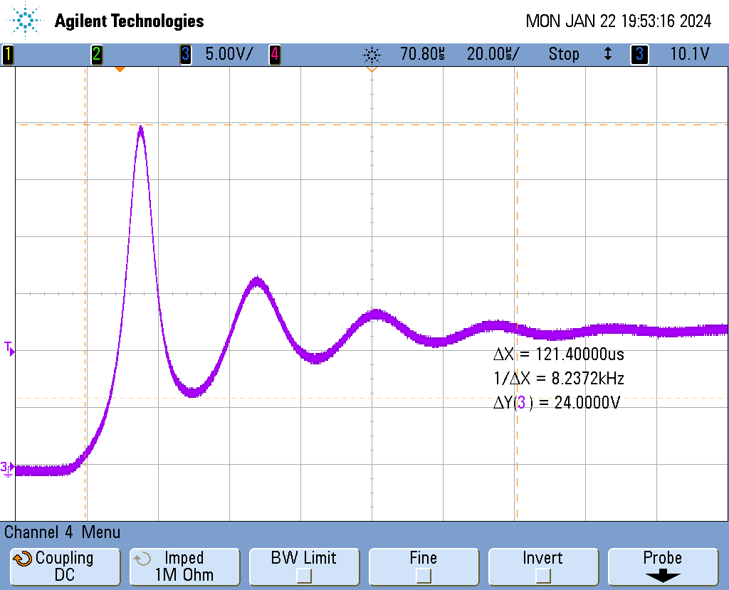
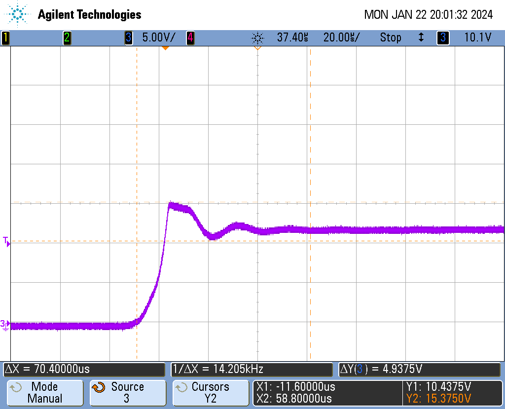
I have also attached a scope plot of the TPS2121 output when the second input is connected. 

There is ~400mA load on the TPS2121 output when the second power input is connected and the output drops low as shown in the scope plot.

I would appreciate it if you could review the information here and give me any feedback as to why I might be seeing the TPS2121 output behave as I do.

Thanks and regards,

Paul

  • Hi Paul,

    Welcome to e2e!

    It looks like IN2 has some overshoot when it just starts up. I see that your OVx pins are set to trigger just above 13V, but IN2 has a voltage spike up to 18V. Can you try the circuit again with R80 depopulated?

    Thanks,

    Patrick

  • Hi Patrick,

    Thanks for the response.


    I tried a number of things, both before and after I posted, in an attempt to resolve the issue I am seeing. One of those was your suggestion to disable the OV detection. I removed both R80 and R19 to disable the OV detection on both channels but unfortunately this didn't fix the problem.

    Other things I have tried:

    - I modified the circuit to set R86 to 10K to increase the hysteresis but I still had the issue.

    - I modified the circuit to set CP2 to GND to configure for VREF mode, but I still had the issue.

    - I changed the resistor divider on PR1 to 10K/1K (with CP2 at GND) and R86 (ST feedback) at 10K but I still had the issue.

    - I modified the circuit to set both CP2 and PR1 to GND, with R86 removed, but I still had the issue.

    - I went back to the original circuit as shown in the post here and added 4.7uF capacitors to GND at the PR1, CP2, OV1 and OV2 pins but I still had the issue.


    To clarify, I don't see the issue on every hot plug. Depending on the configuration I see it with varying degrees of frequency.
    For instance, when I added the 4.7uF caps to the OV1, OV2, PR1 and CP2 nodes it reduced the frequency of the issue but it still occurs about 1 in time in 5 hot plugs.

    Is the interruption I am seeing on the output consistent with a restart of the MUX?

    Regards,

    Paul

  • Hi Paul,

    Thanks for your detailed response, it helps with debugging this issue.

    One more thing I'd like to ask - you mentioned that this happens when one input is active and the other is hot-plugged (I am assuming that the original input is still high). Do you only test this with IN1 active/IN2 hot-plugged? If so, can you try it when IN2 is active and IN1 is hot-plugged also?

    Thanks,

    Patrick

  • Hi Patrick,

    I have tested both configurations (IN1 active/IN2 hot-plugged and IN2 active/IN1 hot-plugged) and I see the issue in both cases. This is with the circuit as shown in the schematic that I have posted above.

    As a test, I modified a board earlier today to change the PR1 and CP2 dividers from what you see in the schematic posted here. I changed the PR1 divider to 44.2K/4.99K and the CP2 divider to 47K/4.99K. The rest of the circuit is unchanged. This gives switchover/switchback voltage levels much closer to the nominal VIN1 and VIN2 levels of 12V than the original circuit.

    This change appears to make the hot-plugging more robust at the lower load currents I have been testing at (~400mA). I can do numerous hot-plugs on VIN1 and VIN2 before I see an issue with this output load level - the issue occurs maybe 1 in 30 or 40 hot-plugs with this change.

    If I increase the output current to ~1.2A I see the issue more frequently, maybe 1 in every 3 or 4 hot-plugs. Again, I see the issue on both a hot-plug of VIN1 or VIN2 with the other input connected and active.

    Any suggestions you have for measurements, test etc. that might help to get to the bottom of this would be appreciated.

    Thanks again,

    Paul

  • Hi Paul,

    Thanks for the information. I see in the waveform you sent in the original post that the hot-plugged INx looks to be stable, but I've seen before that upon zooming into the switchover, it turns out to drop below UVLO threshold and reset the device. That theory would support that increasing the switchover voltage makes the hot-plug more successful and increasing the output current makes it less successful. Can you try repeating the test with a small timescale (maybe 5us/div, or whatever fits the period from switchover until INx is stable)? And, if it turns out that INx is dropping below UVLO and resetting the device just after switchover, then I recommend you increase the capacitance on each input to the output capacitance magnitude. This should add to the load transient performance of the input source.

    Please let me know the results of this testing/theory.

    Thanks,

    Patrick

  • HI Patrick,

    Thanks again for your reply. 

    I have attached a scope plot here of the primary power being connected - the measurement was taken at C11, the 22uF capacitor at the VIN1 pin of the MUX. VIN2 was already connected and stable when VIN1 was connected.

    I measured more or less an identical waveform at C126 when VIN2 is applied with VIN1 already connected and stable. As you can see the maximum voltage seen is ~29V.

    There are TVS Diodes on the inputs at the connector pins but there are Common Mode Chokes after the TVS and before the MUX input pins as can be seen in the schematic above. 

    I removed the Common Mode Chokes L3 and L22 (adding 0 Ohm resistors at R17, R18, R54 and R56) to reduce the series inductance on the inputs and took the same measurements when connecting VIN1 and VIN2. Removing the CM Chokes appears to have a big effect on the measured transients when connecting the power adapters as can be seen in the plot below. The plot below is taken at C11 when connecting VIN1 with VIN2 already connected and stable.

    Even though removing the CM Chokes greatly reduces the ringing I still see the output dropping on some hot-plugs. From looking at the waveform you can see the VIN1 waveform reaches to ~15.5V initially. The OV detection is set to approx. 13.5V on the board I took these measurement on.

    Is the ~20us duration that the voltage is above the OV detection threshold long enough to trigger the OV circuit?

    My next steps are to disable the OV detection on this board (remove R19 and R50) and see if this eliminates the problem. I will also try to add 470uF caps to the MUX inputs if possible - this may be trickier as all components are surface mount and the layout is tight in that area. 

    I will get back to you with the results of these tests in the next day or two.

    Any further ideas or suggestions you have to help me root cause this issue would again be appreciated.

    Thanks and regards,

    Paul

  • Hi Paul,

    Definitely we'd want to avoid the 29V on the inputs, as the abs max ratings on the inputs is 24V. Also, the input drops to ~6V on the rebound of the ringing, and we'd want to avoid this as well as it is presumably after the device has already switched.

    20us is more than enough to trigger the OV circuit - I hope that this is the root cause case, but it looks unlikely to be so.

    Is the most recent test with the original PR1/CP2 resistor setup or the 44k/5k + 47k/5k setup? I would recommend continuing tests with the .../5k setup.

    Also, your previous test with 4.7uF caps on PR1/CP2/OVx makes me think that that acted as a sort of delay that coincidentally delayed switching until the input was stable.

    If you haven't taken the waveforms yet, is it possible to include the ST pin in these tests as well? It will tell us precisely when the device is switching over, and if it is switching multiple times.

    Thanks,

    Patrick

  • Hi Patrick,

    The latest waveforms were taken with the 44k/5k + 47k/5k setup. My plan is to continue testing with these resistor setups as you suggest.

    I will repeat the measurements tomorrow and include the ST waveform. 

    Thanks again,

    Paul

  • Hi Patrick,

    I took some scope plots which included the ST waveform.

    These plots were taken with the 44.2k/5k + 47k/5k setup on PR1/CP2. R19 and R50 were removed to disable the OV detection on the input channels. The Common Mode Chokes were also removed (L3 and L22) to reduce the overshoot we see on applying power to approximately 15.5V max.

    The plot below shows power being applied at VIN1 with VIN2 already applied and stable. As soon as VIN1 is applied ST goes high and the output voltage drops as before. It looks like the MUX selects VIN1 when it is applied but restarts causing the VOUT drop.

    I then, per your suggestion, added 470uF caps to GND at VIN1 and VIN2. This seems to fix the issue. I did numerous connects/disconnects on both VIN1 and VIN2 without seeing an issue.

    The plot below is when VIN1 is applied (with VIN2 already connected and stable) with the 470uF caps connected across the inputs. As you can see there is no ringing on the input waveform. There is ~400mV dip in VOUT which doesn't cause any issue for the downstream DC/DC regulators.

    It appears to me that the TPS2121 has an issue with ringing on the inputs even with the Overvoltage Detection disabled. Adding the 470uF caps removes this ringing and seems to resolve the issue. Does this seem correct to you?

    My plan is to take measurements with the Common Mode Chokes back in the circuit (we would like them in for EMI reasons) and the 470uF caps present to see if that configuration is robust. I will post the results in a day or two when I have completed the testing.

    Thanks again for your help on this.

    Regards,

    Paul

  • Hi Patrick,

    Apologies, I some how inserted the first plot 3 times in the previous post, not sure how I did that.

    Paul

  • Hi Paul,

    No problem, for your knowledge in the future, I believe replies can be edited if you wish to do so.

    Great that adding the 470uF caps to the inputs resulted in cleaner switchovers. However, I do notice that in the last waveform you sent even after IN1 has risen, the ST pin shows that IN2 is active - so if the circuit works after adding the CMCs back, I would double-check to verify that the device is determining the source priority as intended after hot-plugging, and test when each input is removed as well to make sure there are no issues there.

    Thanks,

    Patrick

  • Hi Patrick,

    I have spent some time in the lab testing the PCB with the 470uF caps added to the MUX inputs. I see no issue with this PCB, the MUX functions as expected with no board resets occurring on either connect or disconnect of either power input.

    So, it looks like the addition of the large caps on the TPS2121 inputs has resolved the issue for us.

    Thanks very much for all your help on this, it was greatly appreciated.

    Regards,

    Paul

  • Hi Paul,

    Great, please feel free to respond to this thread or start a new thread if you have any more questions!

    Best in the rest of your design!

    Thanks,

    Patrick