This thread has been locked.

If you have a related question, please click the "Ask a related question" button in the top right corner. The newly created question will be automatically linked to this question.

TPS25947: Output failed shorted to GND

Part Number: TPS25947

I’m using a pair of TPS259474LRPWR  in a design and after a little while of normal use, U5 failed in a worrying manner where the input shorted to the output and to ground internally and let the smoke out. I cannot work out why the eFuse failed because as far as I can tell, the design won’t let any of the pins go beyond their absolute maximum values.

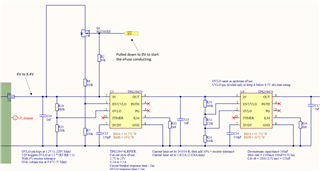
Here is the circuit. The input can vary between 6-8.4V. The EN line gets pulled low off-sheet to switch on Q1 which should in turn start the eFuse conducting.

Is there anything wrong with this design that could allow the eFuse to catastrophically fail?

  • Hi Tom,

    Thanks for reaching out! I will get back by tomorrow EOD this.

    Regards

    Kunal Goel

  • Hi Tom,

    Did U5 fail or U6?

    Regards

    Kunal Goel

  • Hi Kunal,
    U5, as per my original message.
    Thanks,

    Tom

  • I did wonder if a large negative spike could appear at the output of the eFuse since I have no clamping Schottky diode on the output of the eFuse. This would be odd because U5 has failed and not U6 which is why I imagine you were asking which eFuse had failed. Secondly, I have since removed U5 and U6 from this board and replaced them with a mechanical switch so I can try and cut the power any time and measure if there are any negative transients. There weren't any.

    Is there anything else that can be the issue? I'm at a loss about what I can check next. Until I understand what's gone on with this IC, I'm very worried about the rest of my design which has many of these eFuses which I now know can fail short

  • Hi Tom,

    Only reason I could think of is VIN pin abs max violation due to VIN overshoot and VOUT pin going negative. 

    Regards

    Kunal Goel

  • Thanks for checking the design. I didn't think there were any silly mistakes in there but it was re-assuring to have more pairs of eyes look over it. We must have taken either the input or output pins beyond their absolute maximum, so we've added some better ESD protection on the input and put a Schottky diode on the output to ensure the output in can't be pulled below -0.3V by any downstream inductance. Haven't seen a failure since.