This thread has been locked.

If you have a related question, please click the "Ask a related question" button in the top right corner. The newly created question will be automatically linked to this question.

LM5156: LM5156: LM5156/55 output fluctuation with no load

Part Number: LM5156
Other Parts Discussed in Thread: LM5155,

   1385.LM5155_56_Excel_Quickstart_Calculator_for_Flyback_Regulator_Design.xlsx

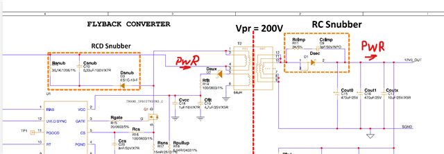
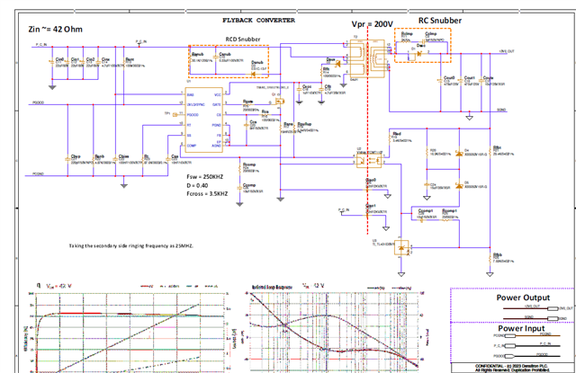
I have designed a DC to DC flyback converter using LM5156. The schematic and regulator design files are attached. I am getting abnormal behaviour. With no load its saw tooth wave over the output giving voltage fluctuation from 5v to 15v. After putting the load more than 8W it becomes stable. As the load is less than 8W it behaves like capacitor charging discharging. By decreasing the output capacitance from 1mF to 500uF the ripple is less for less power (e-g. It works fine after 5W with less output capacitance).

The problem as load takes less power on start up. It fluctuate and the load is not starting up. Please suggest on how it can be fixed. Ideally it should be stable with no load. Is it linked with soft start-up. SS or. Please suggest any solutions.

Thanks.

  • Hi Fahim,

    Thank you for reaching out, regarding your query it seems like your cross over frequency is too low, I would change the COMP pin circuit to what is suggested in the calculator tool and then see if it is more stable.

    You can read more about stability here and this one.

    Hope it helps.

    BR,

    Haroon

  • Hi Haroon,

    The reason of low cut off frequency is because it was driven with 12v input range. In the attached excel sheet if I change the output current to no load approx = 0.02A the loop required slop compensation resistor. I tried over the hardware and it didn't work at all. Is it due to very low cross over frequency? What is the best way to solve it.


    LM5155_56_design_values.xlsx

  • Hi Faheem,

    Please allow us some time to get back to you.

    Thank you

    BR,

    Haroon

  • Hi Faheem,

    Thanks for the update.
    No no load conditions, there will always be a larger ripple on the output as the device cannot maintain such a small duty cycle and therefore starts to skip pulses so the output does not run away.
    However, I fully agree that is ripple should not be in the range of 5V to 15V.
    The compensation is stable based on the quickstart calculator, even though it is slow. In addition, you are operating the device at rather low switching frequency of 89kHz. (The device recommends a minimum fsw of 100kHz)
    If adjustments of the compensation are not possible, I would suggest increasing the fsw. (e.g. 400kHz)
    Do the output caps have a high ESR?
    Low ESR caps are best for filtering switching noise. Ceramic caps are best suited for this, even though they have lower overall capacitance.

    This design already has a secondary side softstart implemented. When you say there is fluctuation at startup with less output capacitance, do you mean you see a hiccup behavior? Maybe a waveform measurement would be helpful to fully understand the issue.

    Best regards,
    Niklas

  • Hi,

    Thanks for coming back. The switching frequency is around 250KHZ. The output is hiccup behaviour. The ESR of output caps is around 10m Ohm.

  • Hi Faheem,

    Thank you for your reply, please allow us some time to get back to you on this.

    Currently our Bandwidth is quite narrow.

    Thank you 

    BR,

    Haroon

  • Hi Faheem,

    Thanks for the feedback.

    I am sorry for this misunderstand from my side regarding the switching frequency.
    You are completely correct that the fsw is set to 250kHz in this configuration, which is well within recommended limits.

    Regarding the hiccup behavior during softstart. We have an app note focusing on improving startup behavior in flyback topology.
    https://www.ti.com/lit/an/snvaa44/snvaa44.pdf
    You might be able to find design improvements with this to stabilize the startup.

    Best regards,
    Niklas

  • Hi,

    The startup issue is solved by putting a PS for LM5156 vcc using same power supply. Transformer is making a lot of noise and output has also alot of ripple. What is the best way to check the RC clamping circuit.

  • Its the noise on the output going to aux side of transformer and causing LM5156 not to work. Pleas look the schematic and suggest on it. Thanks.

  • Hi Faheem,

    For calculating RC and RCD snubbers, I would recommend our power stage designer tool, which comes with calculation tools for both, as well as short explanations on the step-by-step process on adjusting RC values:
    https://www.ti.com/tool/POWERSTAGE-DESIGNER

    Best regards,
    Niklas