This thread has been locked.

If you have a related question, please click the "Ask a related question" button in the top right corner. The newly created question will be automatically linked to this question.

BQ77915: Charge FET turning off and on during charging

Part Number: BQ77915
Other Parts Discussed in Thread: BQ24610,

Hi Everyone

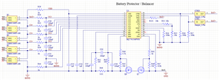
I am using a BQ7791508 on a board with a 5s battery for protection and cell balancing. The board also has a charger based on the BQ24610. When I was testing the board for the first time it looked like it was working well. The battery was charging normally, up to a point. Before the battery was fully charged, I noticed that the the charging was starting and stopping every few seconds. At this point the cell voltages were around 4V and they should charge to 4.2V. Here is the relevant part of the schematic:

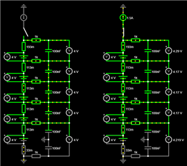
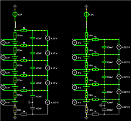
As I was troubleshooting, I determined that the issue was the BQ77915 turning off the charge FET a few seconds after the charging starts. I confirmed this by checking the gate voltage of the charge FET. If I bypass the charge FET, the battery continues to charge normally. This is strange since the BQ7791508 should only disable the charge FET when cell voltages reach 4.2V. At first I thought the charger is maybe applying to much voltage, so I measured the voltages directly over each cell when it is charging every few seconds. The cell voltages when charging are as follows:

S5 = 4.038 V
S4 = 4.043 V
S3 = 4.021 V
S2 = 4.033 V
S1 = 4.060 V

I then measured the cell voltages when charging on the IC's side by measuring over C26, C27, C28, C29 and C31 with the following results.

S5 (C26) = 4.225 V
S4 (C27) = 4.166 V
S3 (C28) = 4.148 V
S2 (C29) = 4.164 V
S1 (C31) = 4.230 V

According to these voltages, the overvoltage fault should occur, but since the actual cell voltages are not so high, the charger keeps trying to charge.

Can anyone please explain this discrepancy in the voltages or give me some advice on how to fix this?

  • Hello Johannes,

    Is the part possibly hitting the over-current in charge protection? If current becomes too high, it may stop charging.

    Table 9-5. Fault Condition, State, and Recovery Methods in the datasheet shows all the cases where CHG could turn-off.

    Best Regards,

    Luis Hernandez Salomon

  • Hi Luis

    For this part, using a 10mohm  current sense resistor, the over current should only be at 6A or more. I am charging at 2A max. Also like I said, the battery was charging fine for a long while before this started happening as the cell voltages got higher. I still believe this is an over voltage fault since I measure 2 cell voltages greater than 4.2V on the IC side. My question is still: Why are the voltages measured on the IC side higher than the voltages measured directly over the cells when charging?

  • Hello Johannes,

    Yes, then that's likely the case. I am not sure why you'd be measuring higher voltages than the cells? Did you see how it looks with an oscilloscope?

    Do you see any leakage currents anywhere?

    Best Regards,

    Luis Hernandez Salomon

  • Hi Luis

    I think I found the problem. After some more testing I realized it is most likely a layout issue. I have cell holders on the board and the series connections between the cells are in the form of traces on the board. First of all these traces were a bit to thin and very long, thus they had a significant resistance that caused a voltage drop between the positive terminal of one cell and the negative terminal of the one above it. Furthermore, I connected the measuring traces for BAT+ and BGND From the high current traces (which were also long and too thin) meaning that they measured the voltage after the drop in the high current traces. I also connected the measuring traces of each cell to the negative terminal of the cell above rather than the positive terminal of the relevant cell. This also created and offset from BGND because of the high trace resistances, even though they are the same nodes.

    I did some calculations for the trace resistances and modeled my layout in a simple circuit simulator. As seen below, when the charge current is off (as seen on the left), the readings are correct, but with the current flowing (as seen on the right) you can see the offsets are almost exactly as my measurements show.

    So by thickening all the high current traces, connecting measuring traces directly to the positive terminal of each cell and adding direct dedicated measuring traces for BAT+ and BGND separate from the high current path, I believe my problem should be solved. The picture below shows the model of my old layout (Left) and my new layout (Right). As you can see the measurements are much more accurate.


    Maybe this can help someone who, like me, forgot their basic electronics knowledge :)