Hi, Expert.
As title description.
Customer try to use MCU control TPS6594x,
How to know TPS6594x work in which state?
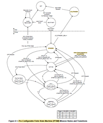
For example, How to know TPS6594 works in "STANDBY Mode" ? I think ,
1. Could we read register from through I2C in STANDBY Mode?
if the question is "yes", What's the register?
2. Do we have any GPIO do indicator each FSM state?
Many Thanks
Gibbs