This thread has been locked.

If you have a related question, please click the "Ask a related question" button in the top right corner. The newly created question will be automatically linked to this question.

TPS63802: Enable pin with 10K ohm series resistor

Part Number: TPS63802

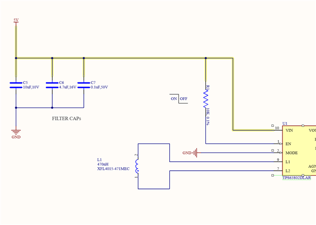
I am currently reviewing the datasheet of TPS63802dlar and have a query regarding the connection between the input voltage (rated at 5V) and the Enable (EN) pin.

The datasheet indicates a direct connection between the EN pin and the voltage input. However, I am thinking of having a 10K resistor in between the input voltage and Enable pin in the circuitry. I am reaching out to seek your professional opinion on whether incorporating a 10K resistor in series between the input voltage and the EN pin would be advisable.

Your insights on this matter would be greatly appreciated, and I look forward to your guidance.

  • Hi  Daniel,

    It is ok with a 10K resister in series. May i know why you want this resister mounted because it is not necessary, a dirrectly connection is ok too.

    Regards

    Tao

  • It's a personal preference on my part, I introduced a 10K resistor between the constant 5V VIN and EN pin to enhance overcurrent protection for the comparator. Although I'm uncertain about its necessity, I conducted a test by shorting the 10K resistor, and the results were perplexing. The output voltage remained at the expected 3.3V, but the current consumption of my usually 10mA load increased to 140mA.

    Upon unsorting, the circuit failed to produce any output, and I observed zero voltage output. The only time it generates output is when the 10K ohm resistor is replaced with a short, but this leads to an inappropriate increase in current consumption.

    Are there any concerns or considerations I should be aware of in this scenario? Your insights would be greatly appreciated.

    Thank you!

  • Hi  Daniel,

    From my side, i think both behavior about shorting or unshorting this resister you observed are unexpected. Could you help try again and  capture the waveform of EN, inductor of current, Vin and Vout?

    Regards

    Tao

  • Readings from Multimeter

    With 10K resistor
    -------------------------
    VIN : 5.04V
    PG (PAD 5) : 0V (I've connected a pull up of 100K with the Vin rather Vout which is 5.04V)
    FB (PAD 4) : 0V 
    VOUT: 0V
    Circuit Power Consumption : 10mA


    With 10K shorted,
    -------------------------
    VIN: 5.04V
    PG : 5.006V
    FB : 0.5V
    VOUT : 3.316V
    Circuit Power Consumption : 147mA

    For the power consumption, I tested with a dedicated module unit (which converts 5V to 3.3V as well). As I have some IC which runs on 3.3V. Found out all together it's 20mA. So when it gets to almost 150mA with VIN - EN shorted, is not making much sense to me.


    Oscilloscope Voltage Ratings
    -- --- --- --- --- --- --- --- --- --- -
    With 10K resistor
    -------------------------
    This is Voltage Input 

    This is EN


    This is Inductor

    This is Vout 


    With 10K shorted,
    -------------------------
    Inductor Waveform


    EN Waveform


    VOUT 3.3V


    I would greatly appreciate it if you could share your insights and thoughts regarding the waveform and readings that were recently provided. Your professional input is invaluable to me, and I believe it will contribute significantly to the ongoing analysis.

    Thank you very much for your time and consideration.

  • Hi  Daniel,

    Seems there is no difference at EN Pin between with or without 10K resister, right?

    Then, it makes me confused, the only impact of this resister should be state of EN and they are actually same. the EN voltage is measured close to device, right?

    Regards

    Tao

  • My apologies, I have uploaded the wrong file for EN (10K without shorted). I am going to make an edit to the previous post and also update the files for Inductor and EN readings to this post. 

    With 10K resistor
    -------------------------
    EN Reading 


    INDUCTOR Reading 


    Thank you!

  • Hi  Daniel,

    Got it,  now it is make sense.  

    Did you measure the value of resister when it is not mounted?

    Regards

    Tao

  • Certainly! I performed the task twice and even replaced the resistor, despite the fact that the resistance was accurate at 10K.

  • Hi Daniel,

    This is strange, you can see the maximum leakage current of EN Pin is 0.2uA. Since the resister is correctly 10k, i do not know why the voltage drop at this resister can be almost 5V, it does not make sense, right?

    The maximum voltage drop at this resister should be 2mV, right? Could you try with a new device? not sure if it is damanged or not.

    Regards

    Tao

  • Hello Tao, 

    Indeed, I am also reaching to a similar conclusion. I've already ordered the parts and upon receiving those, I will do the testing on the new boards. 

    Thank you! 

    Regards,
    Daniel 

  • Hi  Daniel,

    My mistake, they are not same device...Joy
    wait for your update, hope it is a good news.Grinning

    Regards

    Tao

  • Hello Tao, Sure! Smiley I will be waiting for the news. 

  • Hi  Daniel,

    Got it, waiting for your update. thanks

    Regards

    Tao

  • Dear Tao,

    I wanted to provide an update regarding the latest batch of the circuit. It appears that this batch is successfully generating the voltage as intended with a 10K resistor. However, I am still puzzled by the sudden failure of the other chip in the previous batch.

    Additionally, I have a question regarding the behavior of the circuit. I've noticed that when the input voltage ranges between 1V to 1.6V, the output varies between 0.6V to 1.77V. My understanding was that when the voltage falls below a certain threshold, the output should ideally remain inactive. Could you kindly shed some light on why this output range is observed under these conditions?

    Thanks!

  • Hello Daniel,

    Please have a look at chapter 9.3.4 of the datasheet. if the input voltage is below the UVLO threshold, the device is in off state.

    It is possible that some charge is still present on the output capacitor after you reduce the input voltage, but this should decay over time.

    Please check if the output remains low after the output capacitor is discharged. If this is not the case, you might have some path besides the device that charge the output capacitors. Please remove the IC from the board and check if there is still voltage on the output when the input is connected.

    Best regards,
    Brigitte