I am reaching out to seek your expertise in addressing a concern related to the assembled boards for which I have attached the schematic, layout, and 3D view snapshots.
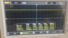
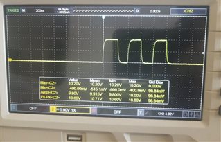
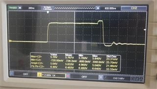
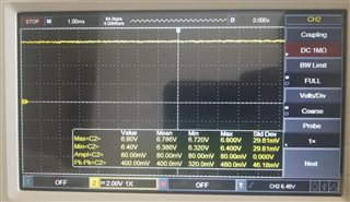
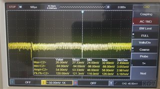
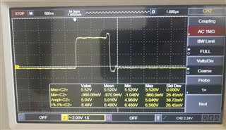
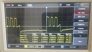
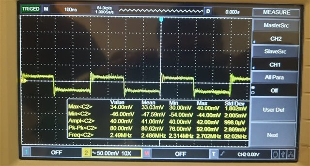
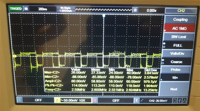
I have identified that all of the boards are emitting higher pitch noise. Some of them are higher than the other. Notably, this noise only starts to emits when a load is connected despite it's rating. Furthermore, I have observed that the issue intensifies when the input voltage is lower than the output voltage, particularly during boost mode operation.
Your insightful feedback on this matter would be highly appreciated. I am confident that your expertise will provide valuable insights into the root cause of these noise issues and guide towards effective solutions.
Thank you in advance for your time and consideration. I eagerly await your professional insights on this matter.
Best Regards
Daniel
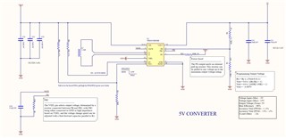
Schematic :
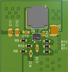
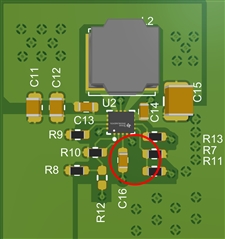
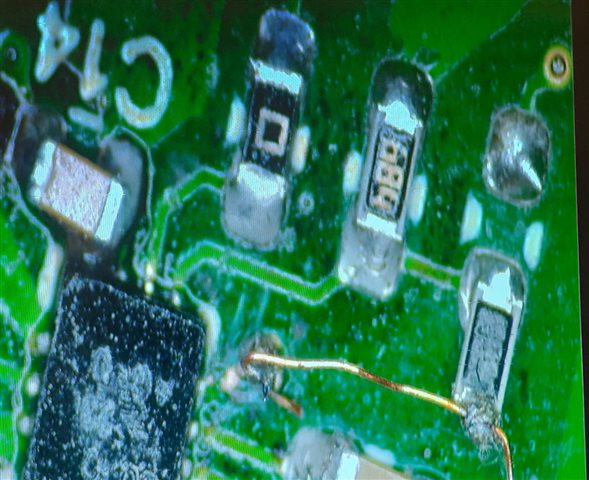
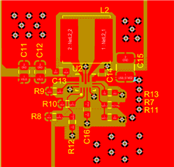
Layout :
3D PCB: