Because of the holidays, TI E2E™ design support forum responses will be delayed from Dec. 25 through Jan. 2. Thank you for your patience.

This thread has been locked.

If you have a related question, please click the "Ask a related question" button in the top right corner. The newly created question will be automatically linked to this question.

BQ27Z561-R2: About the connection between BAT terminal and BAT_SNS terminal

Part Number: BQ27Z561-R2
Other Parts Discussed in Thread: BQ27Z561EVM-011, BQ27Z561

Dear Sir.

 Would it be all right if BAT_SNS terminal is connected to BAT terminal direct?
 BAT terminal is connected to Li-ion Cell plus terminal via R1 resistor (10 Ohm) listed in Simplified Schematic of the datasheet.
 BAT_SNS terminal is connected to Li-ion Cell plus terminal via R2 resistor (1k Ohm).
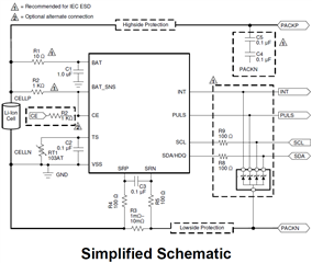
 We think that BAT terminal's rise time is late than BAT_SNS due to R1 and C1 (1uF).
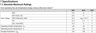
 However, BAT_SNS terminal's absolute maximum rating is VBAT+0.3V.
 Will BAT_SNS terminal ever exceed this specification (VBAT+0.3V)?

Best Regards,

  • Hello,

    Generally the BAT and BAT_SNS lines should be run separately, they should be directly at the battery + node before IR power path losses appear. The voltage and current would need to be very dynamic in order to violate the specification, I don't see this being an issue. I would recommend following the EVM for component and layout help.

    Sincerely,

    Wyatt Keller

  • Dear Keller

     Thank you for your reply.

     Please tell me what is IR power path losses.
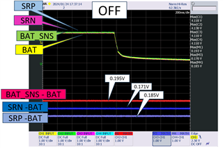
     And, we are concerned about the transient timing of power-on and power-off.
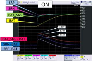
     We used BQ27Z561EVM-011 to check those voltage of BAT terminal, BAT_SNS terminal, SRN terminal and SRP terminal at those timing.
     Please see below data.


     BAT_SNS terminal, SRN terminal and SRP terminal exceeded VBAT+0.3V at power-on timing.
     Should we follow BQ27Z561EVM-011 circuit? Or should we follow the absolute maximum rating of the datasheet?

    Best Regards,

  • Hello,

    The power path IR loss are caused due to high current flow, so you want to connect the voltage sense lines as close as possible to the top of the battery.

    I discussed this with the designer. He mentioned that as long as the BAT_SNS pin has the 1KOhm in series coming from the top of stack, a short transient during battery connection should not harm the device.

    Sincerely,

    Wyatt Keller

  • Dear Keller

     Thank you for your answer.

     I understood that BAT_SNS pin should not harm the device by a short transient during battery connection when R2 resistor(1kOhm) is connected.

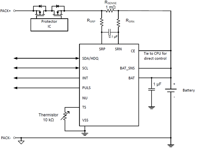
     We designed our product refer to below circuit.
     Rsense is connected to Li-ion Cell plus terminal.


     SRN and SRP pin exceeded VBAT+0.3V at power-on timing, too. (Please see above data.)
     Those pin do not have the 1kOhm on  BQ27Z561EVM-011's circuit.


      Do those pin harm the device by a short transient during battery connection?

    Best Regards,

  • Hello.

    Yes the SRN/SRP pins should not be affected by the transient, as long as the series resistors are populated.

    Sincerely,

    Wyatt Keller

  • Dear Keller

     Thank you for your answer.
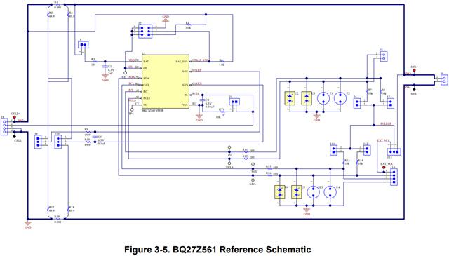
     Is the series resistor of the SRN/SRP pins the SRN:R2+R10/SRP:R3+R9 shown in the Figure 3-5. BQ27Z561 Reference Schematic?

    Best Regards,

  • Hello. 

    The series resistors of the SRN/SRP pins are SRN: R2/R18 (depending on high side or low side sense) and R10, and for SRP: R3/R17 (depending on high side or low side sense) and R9. 

    Regards, 

    Jonny. 

  • Dear Jonny.

     Thank you for your answer.

    Best Regards,