Hello,
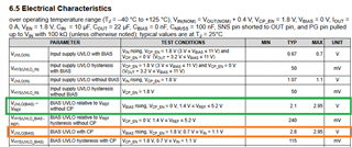
I am using a TPS7A5701RTER on a new board and it will not power on. Here is the pinout and how I have it setup.
Pin 1, 2, 3, 4, 5, and 16 - Tied to 3V8 with 22uF decoupling cap.
Pin 7 - Pulled down with a 65.5k resistor to give roughly a 3V3 output.
Pin 8 - Pulled down with a 4.7uF cap.
Pin 9, 10, 11, 12, 13 - Tied to the output being 3V3.
Pin 14 - Tied to a 3v3_PG signal with a pull up resistor to 3v3 and a 22uF decoupling cap.
Pin 15, 6, and 17 - Tied to GND.
Taking measurements of the board I don't have an output but nothing looks bizarre and there are no shorts going into the chip. The input is valid at 3V8 to pins 1, 2, 3, 4, 5, and 16.
Thank you!


