This thread has been locked.

If you have a related question, please click the "Ask a related question" button in the top right corner. The newly created question will be automatically linked to this question.

TPS65216: Inquiry regarding bit 0 of INT2 Register in TPS65216 PMIC

Part Number: TPS65216
Other Parts Discussed in Thread: AM3352, TPS65218, TPS6521815

Dear TI Expert Team,

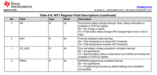
I am writing to seek clarification about the bit 0 of INT2 register in TPS65216.
This bit is described as a "Reserved" in the datasheet.

We are currently evaluating engineering prototypes of a custom-designed board that utilizes AM3352 and TPS65216.
And we have encountered an issue where Linux does not boot up properly on one of these prototype boards.
The occurrence rate of this issue is approximately 30%, with the board sometimes booting up correctly and other times not.
None of the other prototype boards exhibit this problem, but we need to determine whether this issue is due to a design flaw or a defect in the individual component.

We've noticed differences in the INT1 and INT2 register values between successful and unsuccessful boot attempts. The values are as follows.

Successful Boot:
INT1 = 1 0,  INT2 = 0 0

Unsuccessful Boot:
INT1 = 0 0,  INT2 = 0 1

We understand that the 4th bit of the INT1 register relates to the AC_DET status, and we will investigate this on our end.
However, could you provide insight into what the difference in the 0th bit of the INT2 register indicates?

Additionally, even in cases of unsuccessful boot, the DCDC1 to DCDC4 and LDO1 power outputs are functioning normally.
After performing the power-up sequence, these outputs are stably supplying power to the AM3352, that was confirmed by oscilloscope waveforms.

I would appreciate any advice or comment you may have.
Thank you for your support.

Best regards,
Sota Inoue

  • Hi Inoue,

    The TPS65216 is actually a trimmed version of the TPS65218 products. The TPS65218x devices have more power rails than the TPS65216 including two extra load switches (LS2 and LS3)

    If we take a look at the register map for the TPS6521815 for example, we can see that INT1 and INT2 are listed in Section 8.6.4 of the TPS6521815 datasheet.

    Now, if we check register INT2, the bits you are referencing (bit 0 and bit 1) are no longer reserved and are being used as interrupt signals for LS2 and LS3 (current limit faults):

    If we check INT1 bit 1, we find that this interrupt is used for the coin cell battery, which doesn't exist on the TPS65216 version:

    So basically, the reserved bits for TPS65216 are simply unused bits that are left over from the TPS65218 version of the silicon. These bits serve no purpose when using the TPS65216 IC.

    With that in mind, I don't see how these bits could be the reason Linux is failing but I'm also not an expert on Linux applications so I can't say for sure. My recommendation would be to try an A-B-A swap to confirm that it's not an issue with the IC. If the problem follows the board then I would compare the differences between the problematic board and the boards that show no Linux errors. If the IC is working as expected there's not much I can contribute from a Linux perspective.

    Regards,

    James

  • Dear James,

    Thank you for your quick reply!

    I get your point about the "Reserved" bit for future silicon versions. However, we noticed this bit's value changes between successful and unsuccessful booting. Also, on our other prototype boards, the INT2 register value is always 0x00, like in the successful boot cases of the problematic board.

    One more thing, when the boot problem happens, the TPS65216 pulls the nINT output low. This output is connected to the NMI pin on the AM3352 in our custom board circuit. Normally, during a successful boot, the TPS65216 does its power-up and then stops pulling nINT low. We saw this on the oscilloscope.

    So, I think the TPS65216 pulling nINT low might be causing the Linux boot issue. This might be related to the INT2 register's bit 0.

    Could you let me know if this makes sense? Also, if you have any other ideas about why the TPS65216 would pull nINT low, that would be really helpful.

    Thanks again for your help.

    Best regards,
    Sota

  • Hi Sota,

    Are the reserved bits the only interrupt bits that are being set to 1'b? Are there any other bit fields in the INTx registers that could be pulling nINT low or are the reserved bits the only 1'b you are seeing?

    Do you have pins 30,31, 32, and 33 connected to GND?

    Regards,

    James

  • Dear James,

    >Are the reserved bits the only interrupt bits that are being set to 1'b?

    Yes.
    As I wrote in the first post, the differences between successful case and unsuccessful case are INT1 0x10 (successful)/ 0x00 (unsuccessful), INT2 0x00 (successful) / 0x01 (unsuccessful).
    Regarding to INT1, bit 4(AC_DET) "1'b" of successful case is cleared once read the register, and the register changes 0x00 from next read.
    Then the only difference is INT2 bit 0 "Reserved" bit.


    >Do you have pins 30,31, 32, and 33 connected to GND?

    Do you mean TPS65216 PMIC's 30/31/32/33 pins?
    They are described as GND in the datasheet, so of cource they are connected to GND.
    Other circuit connections of our custom board are following to TPS65216 User's Guide (SPRUIP2) and TI's suggestions.
    Pleas see my another post; <e2e.ti.com/.../tps65216-connection-of-tps65216-npfo-nwakeup-nint-pins-for-am3356-processor

    Best regards,
    Sota

  • Hi Sota,

    I don't know why the INT2 bit 0 would be asserted to 1'b in this situation since the pins and power rail structure are unused for the TPS65216 version (pins connected to GND). 

    Have you tried the A-B-A swap with the TPS65216 IC to confirm that the issue is board related and not an issue with the IC? Let me know if the issue follows the specific prototype board or if it follows the IC.

    It sounds like your other prototype boards are consistently powering up as expected. If that's the case then we can compare all the power up waveforms between a successful power up and a failing power up.

    Also please send me your schematic as a PDF for reference. (If you need to share privately, we can set up a direct message space or you can have the FAE email it to me).

    Regards,

    James