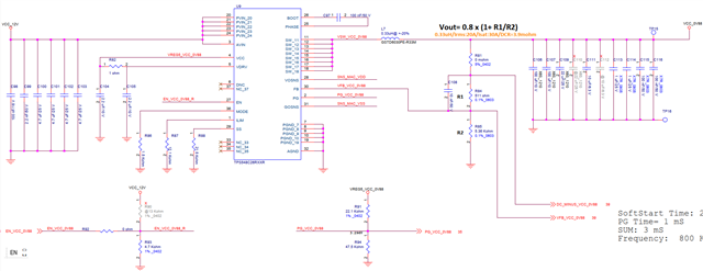
Dear Team,
Could you help to review the schematic as below?


Many Thanks,
Jimmy
This thread has been locked.
If you have a related question, please click the "Ask a related question" button in the top right corner. The newly created question will be automatically linked to this question.
Hi Jimmy,
I will review the schematic and get you back tomorrow.
Thanks,
Nancy
Hi Jimmy,
1. The input caps are too small. Please change C99/C100/C101/C102 to 22uF/25V
2. Separate PGND and AGND. Use a 0ohm resistor or Net tie to connect PGND and AGND together.
3. R81, R85 should be connected to output sense point (not local sense) and also connect to VOSNS and GOSNS. Please refer to Fig 8-1 in the datasheet.
Hope this helps,
Thanks,
Nancy