Because of the holidays, TI E2E™ design support forum responses will be delayed from Dec. 25 through Jan. 2. Thank you for your patience.

This thread has been locked.

If you have a related question, please click the "Ask a related question" button in the top right corner. The newly created question will be automatically linked to this question.

BQ25504: Power management forum

Part Number: BQ25504
Other Parts Discussed in Thread: BQ25570, BQ25505

Hi Team,

Good day!,

We are planning to use BQ25504 for our new product.

Requiting to guide us with the making of the design.

Requirements we planned.

1. Charging the 3.7V, 1000mAh of lithium battery

2. Plan to use the solar cell of KXOB061K08F with a parallel of 3 or 4 cells to charge the battery.

Is our requirement satisfied by the IC function, or do we need to change something?

Thanks 

Ram.

  • Hi Ram,

    The input voltage of the KXOB061K08F is on the higher end of the input voltage maximum rating and higher than the Recommended Operating Conditions of the VIN pin. So it is not recommended to use this input cell with this particular charger.

    If you prefer to keep this solar cell then you may prefer to use the BQ25505 or BQ25570 which can handle the higher input voltage of these solar cells.

    Best Regards,

    Juan Ospina

  • Hi Juan Ospina,

    Good day!,

    Thanks for your suggestion.

    So I would like to go with BQ25570 because Vin is around 5V.

    Where can I get the VBAT pin current value that will change the battery? or will it be approximately equal to the input current?

    What is the maximum current that can be applied to the input pin?.

    Thanks 

    Ram.

  • Hi Ram,

    Where can I get the VBAT pin current value that will change the battery? or will it be approximately equal to the input current?

    The VBAT pin current depends on the input current and voltage. If the voltage of the input is lower than the battery, it is expected that the output current will be lower than the input current since power should be approximately equal.

    What is the maximum current that can be applied to the input pin?.

    The maximum current that can the IC will attempt to pull from the input is 230 mA. This is the Cycle-by-cycle current limit for the charger. The charger will attempt to pull this amount of current, but it is limited by the MPPT point. If input voltage falls to the MPPT point before this current is achieved then the charger current will be limited less than this amount.

    Best Regards,

    Juan Ospina

  • Hi Juan Ospina,

    Good day!,

    I would like to go examine the schematic I have created for my application with you.

    Therefore, if there are any errors or mistakes, kindly assist us in fixing them so that my design is error-free and provide suggestions for improving it.

    I have attached the file to this response.

    Solar cell Charger.pdf

    Thanks,

    Ram.

  • Hi Ram,

    The schematic looks mostly correct, just a few notes on the configuration resistors:

    VOUT: Vout is currently configured to output 3.28V, I just wanted to confirm this is a correct value.

    VBAT_OK_PROG: 3.6V 

    VBAT_OK_HYST: 6.06V

    VBAT_OV: 3.18V 

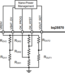
    Based on your notes, I believe you have correct resistor values, they are just placed in the wrong order (e.g. RVS1 and RVS2 are flipped from ROUT1 and ROUT2). Please refer to this typical application notes to identify the correct resistor placements to use in the configuration formulas:

    I believe with the correct configuration you will get 

    VOUT: 1.89 V

    VBAT_OK_PROG: 2.37 V ( This value seems a bit low than what I've seen in the past. It's important to confirm your battery can discharge this low in voltage).

    VBAT_OK_HYS: 2.95 V
    VBAT_OV: 4.14V

    Best Regards,

    Juan Ospina

  • Hi Juan Ospina,

    Good day!,

    Thanks for the correction of my mistake.

    yes, I have planned to take VOUT at 3.3V

    Can you explain these three parameters so that I understand them? got confused.

    1. VBAT_OK_PROG.

    2.VBAT_OK_HYST.

    3.VBAT_OK.

    Thanks,

    Ram.

  • Hi Ram,

    VBAT_OK_PROG is the programmed OK voltage for VBAT / VSTOR. VSTOR / VBAT must be maintained to keep it connected to the system load. If VSTOR drops below VBAT_OK then it is disconnected from the system load and the BUCK is disconnected from power.

    VBAT_OK_HYST is the hysteresis voltage for this threshold. In other words, if VSTOR drops below VBAT_OK_PROG then the system is disconnected. VSTOR now has to rise above VBAT_OK_HYST in order for the system load to be reconnected.

    Together these thresholds control VBAT_OK signal which can indicate to an external load switch or MCU when it needs to be disconnected.

    Best Regards,

    Juan Ospina

  • Hi Juan Ospina,

    Good day!,

    I have corrected the schematic. Have a look and let me know your comments.

    Now VBAT_OK (VBAT_OK_PROG), I have considered it to be 2.9V.

    VBAT_OV  I have considered it to be 4.2V

    VBAT_OK_HYS as 3V

    I have attached the file to this response.

    Solar cell Charger_V1.pdf

    Thanks,

    Ram.

  • Hi Ram,

    The new resistor configuration and values look good.

    Best Regards,

    Juan Ospina

  • Hi Juan Ospina,

    Good day!,


    Thanks for your valuable support.

    Thanks, 

    Ram.