


Hi,
I am designing converter for following specification -
Vin nominal - 12V
Vin min - 11.76V
Vin max - 12.24
Iout - 300mA.
Vout - 5.6V
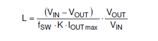
1. Using the Webench Designer I got the circuit and while validating it with equations provided in the datasheet specifically inductor and capacitor selection I found difference in values - L used in the webench simulation is 10uH. Using the below equation for Vin = 12.24V and K selected as 0.3 and fsw = 400kHz the inductor value came across approx. 84.3uH.
and cout value for DeltaV change taken as 0.2V for the DeltaI change(worst case) 0 to 0.3A, K=0.3 and D = 0.46667. Cout>= 8.81uF.
I changed the values in the webench {closest to 84.3uH , 100uH was choosen} to see the loop response but the phase margin and gain margin were bad compared to the one initial given by Webench designer. Attaching the pdf's of both the simulation.
WBDesign38 (3) - circuit given by the Webench designer - no modifications were done.
WBDesign38 (5) - Values were changed and then simulation was run.
4341.WBDesign38 (3).pdfWBDesign38 (5).pdf
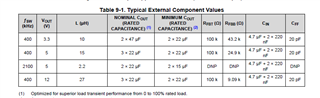
2. In datasheet, following table is given and If I consider using these my inductor ripple current will K = 0.9. How do I select inductor value and verifying that its not affecting the phase and gain margin of converter.
3. Later - from app.note "slvae09b"
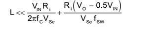
What are the values of Ri and Vse? couldn't locate in the datasheet
Ri = Can I take 240mohm - Rdson of the low side MOSFET ? LS MOSFET used for sensing of inductor current.
Kindly help me
Regards,
Kiran
