This thread has been locked.

If you have a related question, please click the "Ask a related question" button in the top right corner. The newly created question will be automatically linked to this question.

TPS4H160-Q1: Behavior questions

Part Number: TPS4H160-Q1

Hi team,

1. 

My customer want to confirm 2 points for TPS4H160-Q1 behavior. Could you answer for this?

Please see below waveform1: CH1: IN1/3, CH2: SEH, CH3: OUT1, SEL = Low (always).

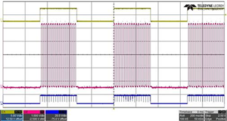
When SEL is L, the output of the OUT1(CH3) pins fluctuates at the timing of SEH(CH2) from H to L.
Does this work correctly according to the IC specifications? They want to monitor two channels so they switch SEH pin.

Waveform2: SEL = Hi (always)

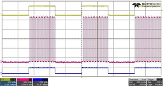
When SEL is H, it doesn't seem OUT1(CH3) pins fluctuates.

2. 

Is it possible that the operation of No.1 is caused by the GND shift due to the VF of the diode of the GND network?
If so, what is the reason for this?
The actual measurement value of VF of the diode was about 0.69 V, so they changed it to Schottky barrier diode, and the actual measurement value was about 0.25 V.
As result, output fluctuation did not occur. 

Regards,

Youhei MIYAOKA

  • Hi Miyaoka-san,

    It is difficult to gain all the information from the waveforms presented. When SEL is low and SEH is oscillating, the sense circuitry is selecting channel 1 and channel 3 respectively.

    It is possible that when selecting channel 1, the sense circuitry being actively mirroring the current is causing the voltage on the GND pin to increase enough to trigger the shutdown for loss of GND.

    Please make sure that the forward voltage of the diode is less than 0.6V under all conditions to avoid any unintentional turn off.

    Thanks,

    Shreyas

  • Hi Dmello,

    Thanks. 

    They are having trouble obtaining diodes(less than 0.6V) that can withstand the test specifications(-250V). Is there any solution? 

    Regards,

    Youhei MIYAOKA

  • Hi Dmello,

    I found "The reverse current protection diode in the GND network forward voltage should be less than 0.6 V in any circumstances. " description.

    Could you share us about 0.6V in detail?

    Regards,

    Youhei MIYAOKA

  • Hi Miyaoka-san,

    Any voltage above 0.6V on the GND pin of the IC can trigger the relative loss of ground protection for the device which causes turn off. This is why we recommend a forward voltage less than 0.6V on the GND pin. We cannot share internal details about the circuitry of the device further than this on public forums.

    Please note that the IV curve of diodes can mean that at lower currents, the forward voltage is lower as well so based on the quiescent and operating current of the device, the forward voltage of the diode can be checked.

    This limitation only exists in our older TPSxHxxx devices. HA,HB and HC, HCS devices do not have this limitation.

    Thanks,

    Shreyas

  • Hi Dmello,

    Thank you!

    Regards,

    Youhei MIYAOKA