This thread has been locked.

If you have a related question, please click the "Ask a related question" button in the top right corner. The newly created question will be automatically linked to this question.

TPS259827LEVM: TPS259827LEVM

Part Number: TPS259827LEVM
Other Parts Discussed in Thread: LM5066

Hello,

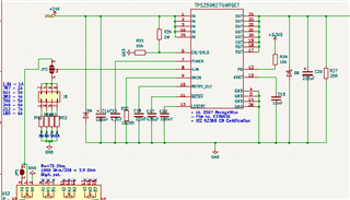
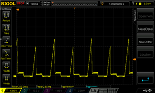
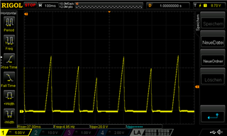
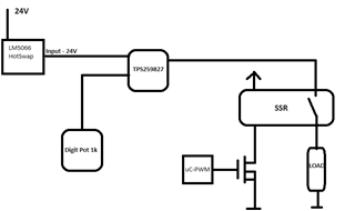
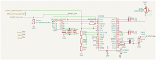
I would like to ask about the chip in the title. I use this chip as an e-fuse on my 24V power line, but I cannot get anything on the output, it is 0,45V and I am wondering wether I made a design failure or not.

On the ILIM pin I use a digital potentiometer to program the maximum current aloowed on the chip, everything else is calculated from the design calculator excel sheet. I attach a schematic snippet. Could you please take a fast look on it if everything looks normal. 

Thank you very much for your help.

Zsolt

  • Hello Zsolt,

    The possible issue is, LDSTRT not grounded. This can result in device not starting up. (Most likely cause in your scenario) 

    If the device still doesn't startup, then please share some waveform of Vin, Vout, input current. 

    Please reply here with any further questions or updates. Click resolved if no other question.

    Best Regards,
    Arush

  • Hello Arush,

    Thank you for your help, it indeed solved my problem. If I may address another issue that I am facing at the moment is, I would like to use this eFuse as a PWM voltage source to my load but it doesn't work I got basically no output, if I look the voltage with oscilloscpoe I got a strange sawtooth signal. I attache 2 picture with 10 and 20% PWM, measured on the eFuse output. To be more precise the efuse output goes to a Solod State Relay and with uController and a mosfet I drive the modulation. Does this mean I cannot use this chip for PWM? If this is the case could you suggest me a sollution for an eFuse with programmable current and suitable for PWM?

    Thank you for your help.

    Zsolt 

  • Hi Zsolt,

    The device is regulating the slew rate. Can you repeat this experiment without any dvdt cap and share the waveforms (Vin and Vout both in same capture please). My reason behind this is without any dvdt cap, you will get fastest slew rate. 

    I will check for the alternatives and will inform you by day after tomorrow. 

    Best Regards,
    Arush 

  • Hi Arush,

    I removed the cap as you seggested but unfortunately it didn't resolve my problem. As you asked I attach the osci pics, and the design concept for better understanding.

    Thank you for your help.

    Zsolt

    Concept:

    Osci pic 1:

    yellow: LOAD; blue:eFuse output; pink: uC-PWM

    Osci pic 2:

    yellow: Input 24V(between LM5066 and TPS259827); blue:eFuse output; pink: uC-PWM

    Osci pic 3

    yellow: Input 24V(between LM5066 and TPS259827); blue:eFuse output; pink: uC-PWM

    after a couple of seconds later eFuse output goes to 0V

  • Hi Arush,

    I would like to modify the title of the topic, and it seems my preavious message is no longer valid. It seems that the eFuse works just perfectly, becaus when I removed the LM5066 HotSwap controller and connected the 24V directly to the eFuse it worked nicely. Let me attach the the pic for that measurement. So it seems the LM5066 needs some kind of redesign, at the moment there is a 5A current limit, but it should be more than enough I dont think thats the issue. Do you have any tipp in mind which direction should I start to investigate?

    yellow: 24V(direct from supply); blue:eFuse output; pink: LOAD

    Hot Swap Controller design

  • Hi Zsolt,

    I will get back to you by EOD.

    Thank you for your patience & Best Regards,
    Arush

  • Hi Arush, 

    If I may add one more comment. I also tried the circuit without eFuse only with Hotswap controller. It worked too. So it seems if I want to use both together than I have a problem.

  • Hi Zsolt,

    Can you tell me your reasoning behind using hot swap controller and efuse? Efuse is like hot swap controller with integrated mosfet. Any specific reason for them?

    I appreciate your patience.

    Best Regards,
    Arush

  • Hi Arush,

    Yes of course. We have a 19" Rack packed with controlling cards, the concept is to have every card a HotSwap controller as a general Power Monitor device connected via I2C, to monitor U/I/P and set an Overvoltage overcurrent threshold. On my card we are talking about I have 2 separate but identical circuits to control 2 heated tubes. I control the temperature for these tubes via PWM 24V. With an extra eFuse I can program the current limit for the circuit on the fly which is a requirement, and I have 2 separate eFuse for the 2 separate circuit parts for different Current limit setup.. 
    Thank you for your help in advance.
    Zsolt
  • Hi Zsolt,

    So, your main concern now is using both hot swap and efuse together for PWM load. I will check this and get back to you by EOD.

    Best Regards.
    Arush

  • Hi Zsolt,

    I apologies for delayed response. Are you still facing this issue?

    I went through this thread again and then realized that initially I understood your issue incorrectly. Now I think I know the issue. I have following question.


    In this waveform, yellow is output of hot swap i.e. input of efuse. Is your input of hot swap also dropping? This blue response looks like efuse is retrying and eventually after pre decided number of retries, it is shutting off. Do you have current probe or can you probe IMON voltage to check the current value. 

    Can you tell more about load? Can you try startup without load and check the Efuse input, output and power supply. If the signals look as expected, then please turn on the load and check these signals again.

    Best Regards,
    Arush

  • Hi Arush,

    Thank you for your email. My load is a Heated Hose, 24V 80W, 6,5 Ohm max. 200 Celsius. I did the measurements you asked for.

    Yellow: Current Probe on the Hot Swap Input (PS output)

    Green: 24V Power Supply

    Brown: Hot Swap out

    Blue: eFuse Out

    PWM: 20%


  • sorry I forgot, that IMON varies (jumping) between 0,3-0,7V

  • Hi Zsolt,

    The above shared waveform is with load, am I correct? 

    After seeing the load details, it looks like the power dissipation at 6.5Ohms resistive load is very high which is causing the device to go into circuit breaker. Then we see multiple retries and after that the device shuts down completely.

    To verify this, you can try this experiment again without load and then turn on the load after the efuse start up or you can redo this with some higher load (less current demand)

    Best Regards,
    Arush

  • Hi Arush,

    I did the experiment you suggested, indeed this is confirmed. I used a 35Ohm power resistor, and from 0-100% PWM it works. Could you suggest a possible sollution If I want to use both Hot Swap and eFuse together to have a functioality mentioned above.

    Channel colors, same as yesterday

    10% PWM

    50% PWM

    100% PWM

  • Hi Zsolt,

    These waveforms look fine to me. So, with higher resistive load, we have lesser power dissipation and startup (rising edge of PWM) won't cause any issue, but your end application uses very low resistance (high current demanding) load which will most likely cause the device to go into current limit and shutdown. You can also verify this in the design calculator. 

    I think you will have to make some design change like change efuse or load specifications to use this configuration. Issue is not connecting the hot swap and efuse, it is in the efuse startup. 

    Best Regards,
    Arush

  • Hi Arush,

    But then why I do not get this issue when I use alone the eFuse without the Hot Swap? It works as it should.

    Best Regards

    Zsolt

  • Hi Zsolt,

    You are correct. It should not have worked when you tried efuse alone. I will check this again.

    Can you confirm once that when you captured this waveform, you bypassed the hot swap and load was same as your original application i.e. Heated Hose, 24V 80W, 6,5 Ohm. 

    Best Regards,
    Arush

  • Hi Arush,

    Yes I can confirm, moreover I am going to make this same Oscilloscope test alone with eFuse, and alone with the HotSwap, when I remember well I didnt get those voltage drops in every cycle when I only the HotSwap used.

    Best Regards

    Zsolt

  • Hi Zsolt,

    I will wait for your test waveforms. Please use both your actual load and higher resistance (less current demanding) load with both devices efuse alone and hot swap alone. 

    Thank you,
    Arush

  • Hi Zsolt,

    I think there is some issue with e2e. I was unable to see your latest reply. I got mail notification about your reply and from there I got to know about it. I feel like we can continue our discussion over e2e direct chat feature.

    Please accept my friend request and I will close this thread. 

    Best Regards,
    Arush

  • Hi Arush,

    Thank you, I beg your pardon I had different more urgent tasks to do. The post you mentioned, I deleted it, because I figured out what was the problem. It seems I need to redesign the the Hot Swap controller to be able to run through more than 10A. I will get back to you after I have the new PCB and tried it.

    Best Regards

    Zsolt

  • Hi Zsolt,

    Understood. Can you please click on resolved to close this thread. You can create new thread if this problem persists with new board and include link to this thread there.

    Best Regards,
    Arush