This thread has been locked.

If you have a related question, please click the "Ask a related question" button in the top right corner. The newly created question will be automatically linked to this question.

TPS546B24A: Schematic Review

Part Number: TPS546B24A

Hi expert,

May I have your support to review customer schematic and clarify some questions that how to fill in the parameters in the spreadsheet? 

Also, would you please correct if any mistakes and update to us to proper setting spreadsheet?


Here are some of their spec and used conditions.

Vout : 0.875V  12A

Fsw : 900kHz

Lo : 0.22uH

Co_POL:MLCC 47uF *10pcs + PSCAP 470uF *2 pcs

Co_Mac:MLCC  1617uf + PSCAP 470uF* 2pcs

Co_eff_total : 3200uF

Cin:22uF 25V 1206 X6S * 4pcs

Cin_eff26.4 uF

Compensation code10  ( seems fast response and lower overshoot & undershoot)

OCP20A ( 20A/12A : 166% )

Soft-Start3ms

Stand alone or multiphase Stand alone 

Q1: if using pinstrap compensation and there are 31 Comp. Code. For example, if customer choose comp. code = 10 and all below calculated value are green, is it typically correct for compensation? 
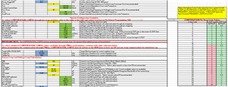
Q2: what would be a recommended BW range for the loop compensation? 

Q3: for the target Vo, is the R2G config correct? Cause they can't match value in the DS.

Q4: how to set PMBus address & interleave if using standalone? 0, auto or anything else?

Q5: MSEL2 (SS, OC, tracking) shows warning, could you please advise what might goes wrong?
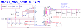
TPS546B24A_3.3V_12A_ExcelCalculator_SchematicLayoutChecklist_20240111.xlsx


Thanks,

Allan

  •  

    will be providing the schematic review, but I will try to answer you questions.

    The description above describes a 0.875V application with a 0.22μH inductor, the Excel file is for a 3.32V application with a 1.0μH inductor.  Please provide the excel tool with the 0.875V application.  

    Q1: if using pinstrap compensation and there are 31 Comp. Code. For example, if customer choose comp. code = 10 and all below calculated value are green, is it typically correct for compensation? 

    Yes, the highest bandwidth compensation option (highest VLOOP) is generally the best options.

    Since the bandwidth with VLOOP = 8 is only 36kHz, you could reduce the output capacitance significantly without sacrificing stability.  That will reduce the overall size and cost.

    Q2: what would be a recommended BW range for the loop compensation? 

    For 900kHz, I would recommend a bandwidth between 45kHz and 120kHz.  Less output capacitance would increase the bandwidth with the same transient performance.

    Q3: for the target Vo, is the R2G config correct? Cause they can't match value in the DS.

    0.875V is not available as a pin-programming voltage.  You will need to select 0.870 or 0.880.  Both 0.870 and 0.880 have pin-programmable resistor options.

    To get 0.875, you will need to program the PMBus value after first power on.

    Q4: how to set PMBus address & interleave if using standalone? 0, auto or anything else?

    Auto-detect allows the part to work as either SYNC_IN or SYNC_OUT, defaulting to SYNC_OUT if no SYNC input is detected.  Selecting SYNC_IN or pulling SYNC up to VDD5 will reduce noise by setting the part into SYNC_IN.

    The PMBus address can be selected based on the addresses used by other devices in the application.  If not used, any address can be selected.

    Q5: MSEL2 (SS, OC, tracking) shows warning, could you please advise what might goes wrong?

    Please share the excel file with the warning.

  • Allan, Kao,

    I have reviewed the customer schematic and agree that the MSEL2 pinstrapping is incorrect if they want to achieve 3ms soft start time. To achieve this, they will need to follow the instructions provided in the Excel tool, which recommends setting Rtop=OPEN and Rbot=SHORT. Please disregard the warning, as it is a mistake in the conditional formatting of that cell, which will be fixed in the next revision of the Excel tool.

    Apart from this, the schematic looks good.

    Thank you,
    Tomoya