This thread has been locked.

If you have a related question, please click the "Ask a related question" button in the top right corner. The newly created question will be automatically linked to this question.

LM5050-1: LM5050-1 damage issue

Part Number: LM5050-1

Hi Team

I sent you about LM5050-1, because customer meets issue.

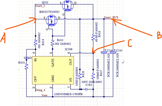
so far I use it as oring-fet controller. Simple description for my application as following:

the maximum input voltage is 50 volts; numbers of parallel module is four, and every module output 40 amps; but LM5050-1 is always damaged when I do test of shorting the input voltage recently. the result is that the IC's IN/GATE/OUT will become low resistance or burned.

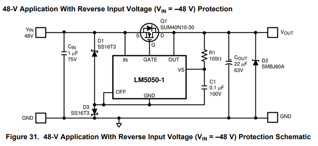
I check the datasheet of figure 31,  which is 48-V application with reverse input voltage protection schematic. 

I want to know the usage of  component D3, 

  • whether is  specified to design for the high input voltage for example above 48V input voltage?
  • if Vin is lower than 5V, and Vbias connected to Vout with RC filter in this application  may cause this problem.

  • Hi Harry,

    By shorting the Input, do you mean conducting an LV124, E-10 test? Regardless, when you short the input, it is important to make sure the device's IN pin doesn't swing negative as it is rated for -0.3V only.

    Since it is a transient, you will need extra components to protect the device. Diode D1 is very critical so that IN pin doesn't negative voltage. Please find theory in  the datasheet.

    Figure 31 in the datasheet is for Input reverse polarity is not applicable in your case.

    Thanks and Regards

    Shiven Dhir

  • Shiven

    Thanks for your respond!

    I double checked the waveform with customer, found there is negative voltage as OC test. and now they plus a TVS diode to protect device.

    And I found in their circuit, there is a inductor as filter, I wanna know if this inductor will worsen the spike?

    and for Cin, Cout selection, if there is any recommendation or guideline?

  • Hi Harry,

    Yes, inductor will worsen the spike. Adding a schottky diode should solve the problem.

    CIN is generally a decoupling cap and can have values according to input noise. 0.1uF can be a good starting point. Whereas COUT is used to hold the output in case of disturbance in input power line. You can go with a higher value cap like 10uF,22uF,100uF,220uF and so on. It varies with use case.

    Regards,

    Shiven Dhir