This thread has been locked.

If you have a related question, please click the "Ask a related question" button in the top right corner. The newly created question will be automatically linked to this question.

UCC27282: Failure:HB short to the ground.

Part Number: UCC27282
Other Parts Discussed in Thread: LM5101C, UCC27211, UCC27211A, LM5101A, UCC27288, UCC27301A-Q1

Dear all,

Background:

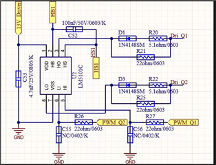
My customer now are designing a 4 switched Buck-Boost converter. And they are using UCC27282 as the gate driver.

To achieve 100% duty cycle for the upper MOSFET. They connected a 12V isolated power supply in the HB(+) and the HS(-)

Experiments:

They have soft-start algorithm that duty cycle of the upper MOSFET will gradually increased with the scale of 1%, frequency is 120K, total time 65ms.

The steady operation stage will be the upper MOSFET consistently conducted which means 100%D and the lower MOSFET will off.

Once they let the output current up to 0.4A, failure will existed. I asked them to test the PIN. They found that the HB is shorted to the VSS.

other information:

input voltage 10-80V, output current max:20A, power:800W

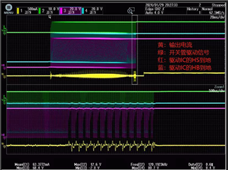
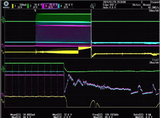
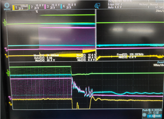
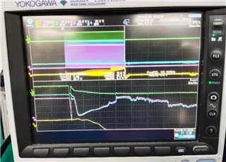
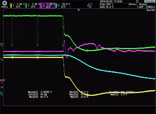
yellow: converter output current  Green: MOSFET driving signal  Red:HS to Ground Blue:HB to Ground.

They have met the same problem when 4SBB works in buck mode. But I asked them to increase Cboot or let the power supply more accuracy to solve the prblem

Thank you 

Yishan Chen

  • Hey Yishan,

    Thank you for your question regarding the UCC27282.

    I think it would be good to take some measurements to see what is going on and I have a few questions.

    1. How many boards are there and how many are they seeing failures on?

    2. If you replace the driver, does the issue persist and fail the second driver? Has an ABA swap been done?

    3. Are any other components failing such as the MOSFETs or the isolated supply?

    4. Can you please take impedance measurements of every pin of a failed device with reference to VSS as well as from VDD to HB? Please do this to a failed unit as well as a good unit with the gate driver off of the PCB and disconnected from everything.

    5. Can you take waveform captures of HB-HS, HB-VSS, HS-VSS, VDD-VSS, HO-HS, and HO-VSS? It would be good if you could get a capture of these while the device is operating right before the failure as well as after the failure occurs.

    Let me know what the results of these questions are and if you have any further questions.

    Thank you,

    William Moore

  • Hi William,

    For question 1:

    They only got one board and the replace different gate driver on it.

    UCC27282 will fail, UCC27211 can work but with a certain level mismatch, LM5101C can work just fine.

    For question 2:

    Yes. And for ABA swap, they haven't fix the problem successfully, so they don't have the condition to do it yet.

    For question 3:

    No.

    For question 4:

    they have measure one good and two failure chips. The first failure chips is in 0.4A load condition, the second one is in 13A load condition/

                                      Good           BAD1             BAD2

    VDD-GND                 High Imp.     223.2k            210.9k

    HB-GND                   High Imp.      52.4               20.8                 

    HO-GND                  High Imp.       0.747M            21

    HS-GND                   High Imp.       0.722M            21.3

    For question 5:

    With respect, Have you seen the upper waveforms?

    Thank you 

    Yishan Chen

  • Hey Yishan,

    The waveform captures that would help understand this issue would be on a smaller time scale to show the zoomed in version of these measurements. It would be good to see the operating state at high PWM before failure as well as if the failure could be captured as well, but it not a capture after failure would be good as well.

    How close to 100% PWM is it getting before failing? It may be a transitional issue between 99% PWM and the 100% PWM DC Mode so these waveforms would help to understand that.

    What is the mismatch that you are referring to for UCC27211?

    As for using a different driver, the UCC27211 has been updated with a newer version as the UCC27211A and the LM5101C is offered as a higher current (closer to the UCC27282) with the LM5101A.

    Let me know what your findings are with the zoomed in scope captures.

    Thank you,

    William Moore

  • Hi William,

    This issue is urgent.

    The waveform is already in the different scale which shows the whole soft start process and the situation before the failure. There are some other waveform. Maybe will help us understand.

    The duty cycle is already in 97.2%

    Let us focus on the 27282 issues.

    Thank you very much.

    Yishan Chen

  • Hey Yishan,

    A scope capture showing the last 1 or 2 periods before failure would be helpful for me to analyze what could be causing this issue. Without this it will make debugging this harder and take longer. This zoomed in capture would allow me to take a look at the transients and rise and fall edges to determine if there is potential negative HS stress causing this issue or HB-HS operating conditions are being violated as well as see possibilities of other potential solutions.

    What is occurring to increase the output current approximately 25ms prior to the failure?

    With the 13V Vdd and 12V isolated supply, as Vf of the bootstrap diode is <1V, the diode is almost always conducting current and could be causing added stress to this high diode stress system. In applications like this where the low-side minimum pulse widths are very small, the diode peak forward and peak reverse currents could be very high. Are you seeing transients on VDD and the isolated supply's voltage potential?

    With this, what is the resistance measurement across the failed part's diode (VDD-HB)? Also, if you have a multimeter that is capable, what is the Vf across these pins as well on the failed units?

    Please provide these waveforms and information regarding the questions that I have asked.

    Let me know if you have any further questions.

    Thank you,

    William Moore

  • Hi William,

    So customer have do another test to record the waveform.

    The 25ms current step is because the E-load. E-load caused this situation at the low current, according to customer opinion.

    And the VDD-HB impendence is 220K, good one is 9.46M.

    And the waveform is as followed. The voltage peak indeed occurred.

    Green: Vgs, Purple: VDD to ground, Yellow: HB-HS, Blue: output voltage of converter

    Maybe is the extremely low duty cycle with the parasitic inductor caused the voltage peak and damage the Pin?

    Do you have any thought about that and how to solve these kind of problem?

    Thank you 

    Yishan Chen

  • Hey Yishan,

    It appears that there is significant ringing or noise on HB-HS at the switching transition. It would be a good idea to zoom in and get a capture of that falling and rising edge to see if that is violating in specs or overstressing the driver.

    What appears to be happening is that it may be violating the HB, HO, HS voltage spec. One thing when operating with an isolated bias supply on HB-HS, is that you need that bias to be at least 0.7V higher than VDD so that there is no interaction between the boot diode and the external bias.

    Of the 2 failed units that you took pin measurements of, the second seems to have a different mode of failure because all three high-side pins are shorted. What is the difference in the operating mode that damaged these two parts?

    Did the MOSFETs fail in any of this? What MOSFETs are being used here?

    We also offer the UCC27288 which does not have the internal bootstrap diode that may be worth trying here so the external isolated bias is then supplying the high-side and not interacting with diode due to a voltage difference in VDD and the bias supply. This can be done as long as VDD and the bias supply are always present. The UCC27301A-Q1 is also a new product that we have that has a diode but is a higher current device and may work here as well.

    Let me know if you have any further questions.

    Thank you,

    William Moore

  • Hey Yishan,

    Were you able to find a solution for this? If so, please let me know what your final solution was. If not, please update me on the status of this and follow up on the questions that I posted above.

    Let me know if there are any questions.

    Thank you,

    William Moore

  • Hey Yishan,

    This thread has been transitioned to email and will be handled there. So I am closing the thread here.

    Thank you,

    William Moore