This thread has been locked.

If you have a related question, please click the "Ask a related question" button in the top right corner. The newly created question will be automatically linked to this question.

TPS62136: Load Transients at High Temperatures Result in Oscillations

Part Number: TPS62136

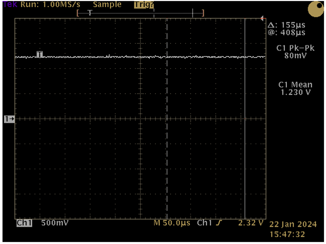
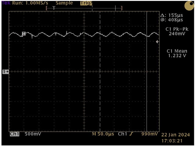
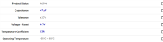
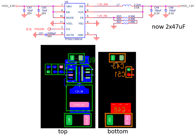
I am powering DDR4 memory with a TPS62136.  The output voltage is 1.2V. The inductor is a Coilcraft XGL4020-222MEC, 2.2uH, 20mohm.  The output capacitors are a pair of GRM31CR60J476ME19L, 47uF, X5R, 6.3V, 1206.  As the transient test is running and the board is heating up, the 1.2V rail will take on a ripple-like oscillation on top of the 1.2V with approximate frequency of 17-20 kHz and amplitude of 200mVpp.  I have not been able to recreate this in WEBENCH simulation.  

  • Hi Eric!

    What is the value of your transient loading? Is there any waveform?

  • The estimated current draw for the DDR4 is 2.5A.  Attached are two scope captures that show how the rail looks before and after it loses it.  

  • Hi 

    For the first figure, can I understand that there is no heating up and the loading of 1.2V is stable.

    For second figure, the boarding is heating up and its loading transition of  from one current value to another value as a circulating?

    Is your load transient frequency is also like 17khz-20KHZ?

    Shuai

  • Hi Shuai,

    Our stress test uses a FPGA to interact with the DDR4 memory with repetitive reads and writes at a high rate of speed.  While this is happening and the board is getting warmer, low level bounces and low amplitude waves intermittently appear on the rail.  Eventually, hints of the waveform in the second figure begin to show up.  Eventually, the power supply gets stuck with the 20 kHz waveform shown above.  It remains even after the stress test has terminated.  It is only resolved by power cycling the board.  

    Eric

  • Hi Eric!

    Thanks for your information. Pls provide me your schematic and layout. Could you pls measurement the load current waveform and SW waveform during the 20Khz waveform happening? Actually, I am still prefer this issue is caused by loading behavior.

    And what is ambient temp when heating? I notice that your output cap has only 85oC limitation.

    BR

    Shuai

  • I do not have a way to measure the load current and the SW pad is not accessible for probing.  The ambient temperature is not getting that hot.  The FPGA is getting into the 80C range, but the DDR4 and TPS62136 are reading in the low 40C range using a bead probe. Here is the schematic and layout.     

  • I noticed your input is only 3.3V. Could check whether your input voltage is lower than UVLO during the issue happened?

    SW waveform is very important to debug. You can solder out the inductor and inserter a wire into connection, then you can probe the SW waveform. For output current, you can also cut off the PCB trace and insert  a wire to use current probe.

  • Hi Shuai,

    I checked for UVLO; the voltage is solid and well above the threshold.  The inductor pads are difficult to get to.  I can almost get a 30ga wire under the part, but I didn't push that further.  One thing we have tried that looks promising is attaching an additional feed-forward capacitor on the top feedback resistor.  That keeps the output voltage very stable even after stress testing the DDR4 at higher temperatures.  SLVA289B was most helpful.  We used WEBENCH transient simulation to estimate the cross-over frequency for the Cff calculation.  We're going to test more boards with this modification today.  

  • Hi Eric,

    Good to know that Cff may help.

    Usually Cff is only used to improve the loop under 100kHz frequency.

    Maybe the 200uF output capacitance is too large and limit the bandwidth below 100kHz, also the higher temperature causes the poorer loop.

    You can also try to reduce the output caps to 1*100uF or 1*47uF to see if there's any improvement.