This thread has been locked.

If you have a related question, please click the "Ask a related question" button in the top right corner. The newly created question will be automatically linked to this question.

TPS25751: BQ25756

Part Number: TPS25751
Other Parts Discussed in Thread: BQ25756

Hi TI,

We want to develop a portable charger with TPS25751 and BQ25656, controlled over I2C from microcontroller. Due to two Type-C ports, we designed to use two pairs of TPS25751 and BQ25656:

The questions are as following, could you kindly give some suggestions? Thanks.

1.Since TPS and BQ are both controlled by MCU via I2C, how do they coordinate under this circumstance? i.e, what register should we read from TPS to configure BQ, and vice versa?


2.Without MCU control, what would happend if the following situations occur?

(1)Both Type-C ports are connected to connected to the chargers with the same specification respectively. For example, Port-1 connects with 20V, 3A charger, Port-2 connects with 20V, 3A charger. Would the charger current to Battery be the sum of BQ-1's and BQ-2's output IBAT?

(2)Type-C ports are connected to the chargers with the different specifications respectively. For example, Port-1 connects with 20V, 3A charger, Port-2 connects with 5V, 1A charger.

(3)Port-1 connects with charger, Port-2 connects with consumer such as mobile phone.

  • Hi Alex,

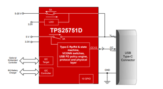
    The TPS25751 can be configured to control the BQ25756 over I2C. Because the TPS25751 does not support I2C multi-master, you would only be able to connect the BQ I2C lines to the TPS part, but the TPS25751 does support 'I2Cw' and 'I2Cr' 4CC commands that enable I2C passthrough from the target to controller  I2C ports. This could be an option for the system architecture instead of what you currently have, and may make the implementation simpler.

    We have up to 4 unique I2C addresses.

    1.Since TPS and BQ are both controlled by MCU via I2C, how do they coordinate under this circumstance? i.e, what register should we read from TPS to configure BQ, and vice versa?

    Coordination will occur through I2C, primarily through triggering off of interrupts from the PD and updating the BQ accordingly. 

    The coordination can be boiled down to reading the status of the PD controller, and then setting registers in the BQ part.

    Key Status messages/System States:

    • Power On
      • No Specific Register
      • Need to configure the BQ part according to system requirements. (i.e. operational mode, charge current/voltage, etc.)
    • Fault event/detach/standby/attach
      • Status (0x1A)
      • Need to configure the BQ part according to system requirements. (i.e. operational mode, charge current/voltage, etc.)
        • Need to know current power connection (source/sink)
    • New source voltage negotiated
      • Active RDO (0x34). The PDO definition can be found in more detail the USB-C PD Spec (found here)
      • Update BQ part with voltage and current
    • New sink voltage negotiated
      • Active RDO (0x34). 
      • Update BQ part with voltage and current.

    There may be may be more registers and behaviors that you will need to implement, but these should cover the simplest behavior.


    We do not have any App Notes for this specifically, but I would recommend looking over the 7 bullet point events on page 6 of the document below. This is for different parts, but it will give you a basic idea of the messages we need the PD controller to send. Unfortunately, this is for sourcing only, so is limited in scope.

    https://www.ti.com/lit/ab/slvaeq7/slvaeq7.pdf?ts=1706809399033&ref_url=https%253A%252F%252Fwww.ti.com%252Fproduct%252FTPS65987D


    (1)Both Type-C ports are connected to connected to the chargers with the same specification respectively. For example, Port-1 connects with 20V, 3A charger, Port-2 connects with 20V, 3A charger. Would the charger current to Battery be the sum of BQ-1's and BQ-2's output IBAT?

    I am not sure about the functionality of the BQ25756 parts, and would recommend you open another E2E thread with this question specifically about those parts.

    From the PD perspective, the ports will negotiate the 20-V 3-A contracts on each port, and update the BQ part with the necessary voltage and current information to limit the power draw of the BQ device. I am not sure what happens on the output of the BQ part.

    (2)Type-C ports are connected to the chargers with the different specifications respectively. For example, Port-1 connects with 20V, 3A charger, Port-2 connects with 5V, 1A charger.

    Not sure about this question. If the charger is charging the same voltage and supports parallel operation, you may be fine. The BQ should handle the power conversion.

    (3)Port-1 connects with charger, Port-2 connects with consumer such as mobile phone.

    The PD controller will configure the port-1 BQ in charge mode, and the port-2 BQ in reverse mode. Functionally I do not see any issues, but have not seen this done in practice.

    Thanks and Regards,

    Chris

  • Hi Chris,

    Thanks a lot for your detailed response.

    Because the TPS25751 does not support I2C multi-master, you would only be able to connect the BQ I2C lines to the TPS part,

    "TPS25751 does not support I2C multi-master" means this design is unreasonable? For clarity, in our design, there's only one master which is MCU on I2C communication. Take I2C-1 for example,

    MASTER: MCU

    SLAVE: BQ-1, TPS-1(BQ-1 and TPS-1 does NOT communicate with each other via I2C)

    MCU communicates with BQ-1 or TPS-1 on different target address.

    Of cource TPS is master on I2Cc(We use this to connect TPS with EEPROM), but on I2Ct the master should be MCU, only one master, right?

    I am not sure about the functionality of the BQ25756 parts, and would recommend you open another E2E thread with this question specifically about those parts.

    OK, I will open another E2E thread, thanks again for your explanation from the PD perspective.

  • Hi Alex,

    Sorry for the confusion, that initial paragraph was explaining an alternative to your initial proposal.

    The TPS25751 can be configured to control the BQ25756 over I2C. Because the TPS25751 does not support I2C multi-master, you would only be able to connect the BQ I2C lines to the TPS part, but the TPS25751 does support 'I2Cw' and 'I2Cr' 4CC commands that enable I2C passthrough from the target to controller  I2C ports. This could be an option for the system architecture instead of what you currently have, and may make the implementation simpler.

    This first comment and the block diagram below it were suggesting an alternative way of setting up the system.


    "TPS25751 does not support I2C multi-master" means this design is unreasonable? For clarity, in our design, there's only one master which is MCU on I2C communication. Take I2C-1 for example,

    MASTER: MCU

    SLAVE: BQ-1, TPS-1(BQ-1 and TPS-1 does NOT communicate with each other via I2C)

    MCU communicates with BQ-1 or TPS-1 on different target address.

    Of cource TPS is master on I2Cc(We use this to connect TPS with EEPROM), but on I2Ct the master should be MCU, only one master, right?

    Your system is good with regards to multi-master. I mentioned multi-master when trying to explain the alternative


    To summarize and bring everything together, your initial proposal (System architecture, I2C connections) will work fine. Having an MCU be the single I2C master and having the TPS and BQ parts as I2C slaves will work.

    The first part of my response was proposing an alternate way, where the TPS25751 would be the I2C master to the BQ25756, and the MCU would be I2C master to only the TPS25751. The reason I proposed this is because the TPS25751 has capability to control the BQ25756 directly, and could reduce the development efforts of the MCU code.

    Either option will work.

    I spoke with a member on the team, and there are some additional events/ interrupts you may need to be aware of. Please give me a week to check these over and I'll provide you an update.

    Thanks and Regards,

    Chris

  • The first part of my response was proposing an alternate way, where the TPS25751 would be the I2C master to the BQ25756, and the MCU would be I2C master to only the TPS25751. The reason I proposed this is because the TPS25751 has capability to control the BQ25756 directly, and could reduce the development efforts of the MCU code.

    Understood.

    I spoke with a member on the team, and there are some additional events/ interrupts you may need to be aware of. Please give me a week to check these over and I'll provide you an update.

    OK, thanks a lot. 

  • Hi Chris, 

    I spoke with a member on the team, and there are some additional events/ interrupts you may need to be aware of. Please give me a week to check these over and I'll provide you an update.

    Could you kindly give the update mentioned?

  • Hi Alex,

    Sorry for the delays, the thread disappeared from the dashboard. I'll provide the updates this week.

    Thanks and Regards,

    Chris

  • OK, looking forward to your response this week, thanks.

  • Hi Alex,

    Thanks for your patience, here is the additional information.

    Thanks and Regards,

    Chris

  • Hi Chris,

    Could not see the additional information you mentioned. Could you kindly post it again? Thanks.

  • Hi Alex,

    Sorry about that, I thought it was added.

    Please let me know if you can view this pdf.

    EC_Controlled_Supply.pdf

    Please understand that this is a basic suggestion for implementing these events, and you can and may make changes if you need additional features or checks.

    Thanks and Regards,

    Chris

  • Please let me know if you can view this pdf.

    Yes, thanks a lot.

    For this pdf, we have some more question as following, could you kindly explain?

    When as Source,

    (1) What does 'Enable DC/DC at 5V for implicit Contract' mean? In our design, PP5V is acquired via Boost/Buck circuit from battery, does it mean enablng the Boot/Buck circuit here?

    (2) Why is 'Int_Event = Sink Transition Completed' used instead of 'New Contract as Provider'?

    (3) Then 'Enabled DC/DC for RDO voltage and current', what exactly is the operation? Which register do we need to configure?

  • Hi Alex,

    (1) What does 'Enable DC/DC at 5V for implicit Contract' mean? In our design, PP5V is acquired via Boost/Buck circuit from battery, does it mean enablng the Boot/Buck circuit here?

    Per the USB-C PD spec, before any USB-PD contracts are negotiated, a 5-V contract is negotiated per the type-C spec using resistive dividers on the CC lines. This is what we call the Implicit contract. Upon connect, you will want 5-V present for the implicit contract.

    (2) Why is 'Int_Event = Sink Transition Completed' used instead of 'New Contract as Provider'?

    The "PS_RDY" message is sent by a USB-C PD source when it is ready to provide the negotiated voltage. You will need to set the voltage on the DC-DC before PS_RDY.

    (3) Then 'Enabled DC/DC for RDO voltage and current', what exactly is the operation? Which register do we need to configure?

    Once a USB-C PD contract has been negotiated, the Active RDO register will update with the agreed upon contract. The requested PDO (Power Data Object) will be populated in the Active RDO Register, and specifies the voltage and max current. You need to read these values from the TPS25751 register, and then program the DC-DC in the system to provide that voltage and current. (setting output voltage and Overcurrent)

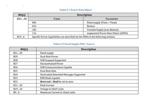
    You will need to look into the PD spec to better understand how the PDO (Power data object) is formatted. The information you need for Fixed PDOs is found in table 6-9.

    https://www.usb.org/document-library/usb-power-delivery

    Thanks and Regards,

    Chris

  • Hi Chris,

    Thank you so much for your detailed explanation. I would read the PD spec to learn more details.

    But from my point of view, TPS25751 is designed to handle USB Type-C conneciton and power negotiation automatically, according to the PD spec. Still take the above Source role for example, once the Type-C was set to act as Source, it could manages the necessary communication and power control without requiring constant intervention from MCU.

    So should we consider the details such as 'Enable DC/DC at 5V for implicit Contract', 'Enabled DC/DC for RDO voltage and current' for MCU control? i.e.,  suppose we only provid PP5V supply and the necessary VIN_3V3 power without MCU's control, could TPS25751 work normal as Source to provide 5V, 9V or the above power to the consumer such as mobile phone?

  • Hey Alex,

    But from my point of view, TPS25751 is designed to handle USB Type-C conneciton and power negotiation automatically, according to the PD spec. Still take the above Source role for example, once the Type-C was set to act as Source, it could manages the necessary communication and power control without requiring constant intervention from MCU.

    The TPS25751 is capable of managing the communication for power control itself, but only when it acts as the I2C master for the BQ device. If you remember, earlier I suggested you use an architecture that looks like this

    instead of what you had initially proposed.

    Because the TPS device does not support multimaster, it would need to be the only I2C Master device connected to the BQ I2C bus. Because you chose an architecture where the TPS part is not the I2C master, it requires the MCU to manage the BQ chip instead.

    So should we consider the details such as 'Enable DC/DC at 5V for implicit Contract', 'Enabled DC/DC for RDO voltage and current' for MCU control? i.e.,  suppose we only provid PP5V supply and the necessary VIN_3V3 power without MCU's control, could TPS25751 work normal as Source to provide 5V, 9V or the above power to the consumer such as mobile phone?

    The TPS25751 is designed to handle the power negotiation automatically, but the system architecture you chose (where an MCU controls the PD and the BQ) requires that the MCU controls the BQ part to set the correct voltage.

    To source voltage, the TPS25751 needs a power supply to provide the 5/9 volts at the PPHV pin (5-20 V). If the TPS25751 is I2C master for the BQ part, it can configure the BQ to provide the correct voltage at the appropriate timing.

    In your system, the TPS25751 is not the I2C master for the BQ part, so you need the MCU to configure the BQ to provide the correct voltages.

    Thanks and Regards,

    Chris

  • Hi Chris,

    Got it. Thanks for your patient and detailed response these days.

  • Hi Alex,

    You're welcome. If you have follow up questions related to this thread, please continue using this thread. If you have any new questions not directly related to the issues in this thread, feel free to submit a new thread.

    Thanks and Regards,

    Chris

  • Hi Chris,

    Get it, thanks.

  • Hi Chris,

    We had some issue when using TPS25751 as Source. It's a bit complicated, so a new thread was submitted. Could you kindly help to analyze? Thanks.

  • Yeah, i'll help take a look.