


Other Parts Discussed in Thread: LM3478
Hello, good day. Our customer have a problem :
Does the lm3478 chip control the voltage loop and current loop together? For example,
 in this picture, during normal operation, if the input voltage and output voltage remain unchanged,
 will the load change current sampling voltage value limit the duty cycle?
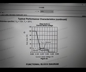
The FB pin voltage is 0 and the current sampling voltage has not reached 0.325v. Will the IC continue to work in the current loop?
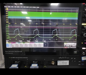
The feedback winding is short-circuited and the FB pin voltage is 0V, but the 3478 is still working (there is a driver output).
The problem is that the fb voltage is 0, why does it continue to work?
 Channel 1 is the feedback winding voltage, channel 2 is the fb voltage, channel 3 is the drive, and channel 4 is the current sampling voltage.
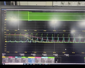
Channel 1 is the feedback winding voltage, and channel 2 is the fb pin voltage. The picture above is the waveform of the feedback winding short circuit
