This thread has been locked.

If you have a related question, please click the "Ask a related question" button in the top right corner. The newly created question will be automatically linked to this question.

LMG1020: there is no output from lmg1020

Part Number: LMG1020

Hi TI expert

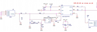
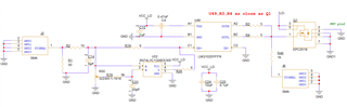
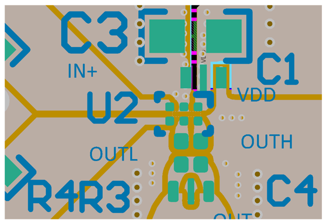
When I was debugging the lmg1020, as shown in the figure below, I used a signal generator to generate a signal with a period of 1MHz and adjustable pulse width to input to the J2-SMA connector, and tested the LMG1020 output signal in J6. The signal amplitude is 2.5V, i.e. 2.5V high and 0V low. R20 is no welding, and the signal is input to the LMG1020 via R19

When the signal pulse width is > 6ns, the waveform can be seen through the oscilloscope from R19 and J6. But when adjusting the signal generator's pulse width < 6ns, I can see the signal at r19 and I can't see the signal at J6. What is the reason for this?

Thanks

  • Hi li,

    While 2.5V is in the range for the IN high threshold, I would recommend a higher signal, like 3.3V (nothing higher than your VDD). Once that is adjusted, please check to see if there's any output signal present by measuring directly at the OUT pins of the LMG1020, as I have a feeling those large output resistors may be a cause of the issue.

    Thanks,
    Rubas

  • Hi Rubas

    I changed the resistance of R3 and R4 to 0Ω,and remove r46. The signal is still 2.5V, because the maximum value of the signal generator is 2.5V. Adjusting the signal generator's pulse width < 6ns, I can't see the signal at J6. 

    I bought your evaluation board LMG1020EVM-006. With a 2.5V signal input and a pulse width of 3ns, the lmg1020 has an output signal. What items do I need to check 

  • Hi li,

    Did you check the signal directly at the output pins? Removing R46 would create a break between the output of LMG1020 and J6, so there wouldn't be any signal at J6 anyways. Please send waveforms of the input and output signals that are measured directly at the IN/OUT pins of the LMG1020 for pulse widths over 6ns and below 6ns. You can also make sure that the VDD bypass capacitors are as close to the device as possible in the layout.

    For the EVM, did you make any changes to the board? Also, please let me know which test points you used to measure the signals.

    Thanks,
    Rubas

  • Hi Rubas

    I checked the signal at r3 or r4, and there is no signal waveforms for pulse widths below 6ns.

    The VDD bypass capacitor is on the left. The distance from cap to lmg1020 is about 151mil. 

  • Hi li,

    Because the LMG1020 is a very fast driver, it is critical that the bypass capacitor is very close to the device. Here is an example layout from the datasheet, where the first one is just using a decoupling cap, and the second is using both the decoupling cap and feed-through (similar to your schematic):

    You also mentioned that you used our LMG1020 EVM. Did you make any changes to the board before using it to test it with 2.5V IN and 3ns width?

    Thanks,
    Rubas

  • Hi li,

    As it's been over a month without a response, I will assume that the problem is now solved, and I will be closing this thread. If you have any more questions, please feel free to respond to reopen the thread.

    Thanks,
    Rubas