This thread has been locked.

If you have a related question, please click the "Ask a related question" button in the top right corner. The newly created question will be automatically linked to this question.

UCC256302: IPolarity detection threshold by ISNS pin

Part Number: UCC256302

Hi Team,

I have inquired about this in the past, but I would like to confirm it again.

UCC256302: IPolarity detection threshold by ISNS pin - Power management forum - Power management - TI E2E support forums

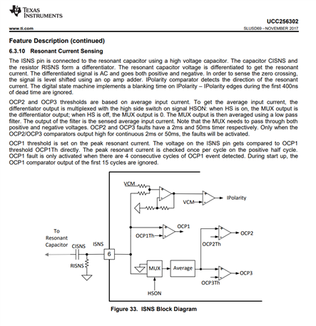
There is a description on the data sheet, "If there is no slew detected, IPolarity signal is used. The next gate will be turned on at the next IPolarity flip event."

What is the threshold for detecting IPolarity flip events?

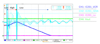
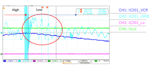
Please see waveform below;

-CH2 LowSideINV_Vds

-CH3 LowSideINV_Vgs

-CH4 ISNS Pin


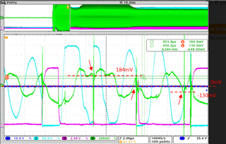
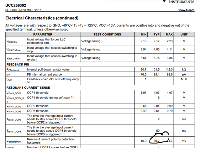
According to the data sheet and previous answers, the threshold value is 44.7/2mVmax above and below the 0V standard, but what could be the reason why it is actually detected (ON) at 180mV?

Please tell me the factors that are detected with a threshold higher than hysteresis.

Please respond ASAP.

Best regards.

  • Hi,

    We don't recommend this part for newer designs. 40x is a pin-to-pin replacement part for 30x. So, please try to switch the parts.

    I am not sure about the threshold value of the ISNS pin voltage that is required in order to turn on the next gate pulse in case of ZCS event. It's not mentioned in the datasheet explicitly. So, I will have to reach out to IC Design team for this.  Please expect the delay in my response.

    Regards

    Manikanta P


  • Hi ,

    We have received similar answers for the 30x series in the past, but we have confirmed that the same mode occurs even when using the 40x series.

    1.Please provide additional information. Is the hysteresis width the value of the ISNS pin? Or is it the value in the internal comparator?

    2.How do you check the hysteresis value on the datasheet? We would like you to show us the actual waveforms that your company has confirmed.

    Please reply as soon as possible.

    Best regards.

  • Hi,

    I have reached out to Adam regarding this. He is going to respond early next week.

    Regards

    Manikanta P

  • Hi,
    I'm waiting for Adam's reply.
    Please reply as soon as possible.
    Best regards.

  • Hi Mani,

    customer mention that same behavior is observed at UCC25640X, so you could help on it, and the PWM is continue switching.

    Hi user6304160,

    I highlight your question to AE manager, so he will take care of it.

    thanks.

  • Hi team,

    Do you have an answer yet?

    Add information here.

    The waveform below is the waveform when burst operation continues. It looks like the Ipolarity detection is incorrect.

    We believe that ZCS detection has caused the state to wait for Ipolarity detection.

    At the Low timing, vibrations of about +120mV occur on CH2, but ISNS cannot detect the polarity.

    Please answer quickly.

    Best regards.

  • It's been over a month and no response.
    please answer immediately.

  • Hello,

    Mani was busy and asked me to look into this for him and you.

    I reviewed the data sheet and found the block diagram in figure 33.  VCM is 3V on the I polarity comparator.

    So when ISINS crosses 3 V the polarity comparator will change states.

    The trip point for the IPolarity comparator change states when VISNS-VCM crosses the VCM threshold.  

    The IPolarity comparator has 30.7 mV of hysteresis.

    If this comparator is not working it would be because the change in the ISNS signal is less than 30.7 mV.  Try increasing the size of your ISNS resistor to see if things improve.

    The following link will bring you to a design tool that will help you properly setup the ISNS pin.

    https://dr-download.ti.com/design-tools-simulation/calculation-tool/MD-I6Djg7YoC0/01.00.00.0B/sluc634b.zip

    Regards,

  • Hello,

    ISNS swings based on 0V, and should be added to the VCM reference by internal amplifier A. Therefore, I think the answer that ISNS detects polarity at 3V is incorrect. Please check again.

    Also, please clearly answer whether the hysteresis at the Ipolarity comparator is 30.7mV or the hysteresis at the ISNS pin is 30.7mV.

    Regards,

  • Hello,

    A is an op amp and not a comparator, so the hysteresis is for the Ipolarity comparator.  Op Amps do not have hsytersis in general unless it is added to make them a comparator.

    Reviewing the block diagram:

    When the Ipolarity + is greater than VCM IPolarity is high.

    When the + of the Ipolarity sees less than VCM - VIplarityhyst  it will change to low.

    The voltage at Ipolarity + should  be (VISNS + (VCM-VISNS)/2)*2.

    Regards,

  • Hello,

    I recognized the hysteresis listed on the data sheet as the value of the Ipolarity comparator.

    Please let me know in addition below.

    Q1. Please tell me the hysteresis value at the ISNS pin.

    Q2. Please tell me the amplification factor of A's op amp.

    Regards,

  • Hello,

    Q1:  Ipolarity comparator has 30.7 mV of hysteresis.

    Q2. The  open loop gain of Op Ams is generally 60-80 dB.  The gain with feedback for Ipolarity Comparator pin can be generated by algebraically solving following equation for (Ipolarity Comparator Non Inverting Pin)/VISNS

    Ipolarity Comparator Non Inverting Pin =  (VISNS + (VCM-VISNS)/2)*2.

    Regards,