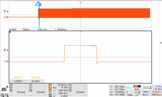
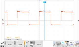
In the use of TI LMR54410, the test found that the SW foot negative voltage exceeds the standard problem
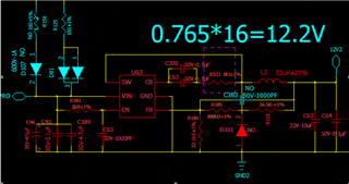
Test conditions: input Vin = 24V, output Vout = 12V; startup, SW foot negative voltage to -4.8V; normal operation, SW foot negative voltage to -2.4V, more than the specification of -0.3V, waveforms see attached.
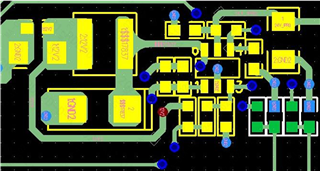
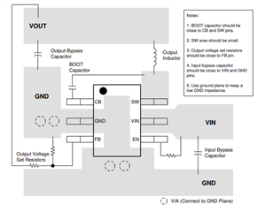
Below is the schematic diagram and PCB for reference.
Is there any related design problem。Please kindly help to provide some design or improvement suggestions