This thread has been locked.

If you have a related question, please click the "Ask a related question" button in the top right corner. The newly created question will be automatically linked to this question.

LMR36520: Expecting 24V but no output

Part Number: LMR36520

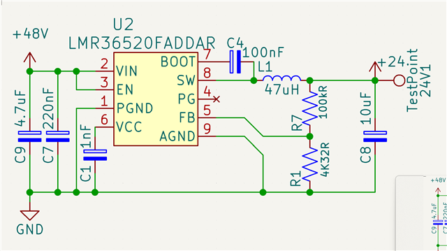
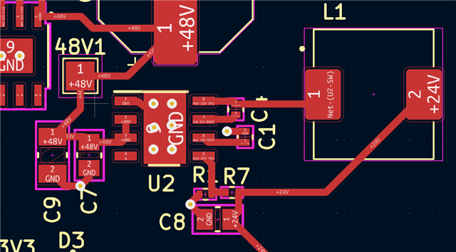
I'm developing a POE board and Input is 48V from the ethernet Jack. The board is a 4 layer board with the 2 middle layers being ground planes. I referenced this circuit on WebBench, but mistakenly changed CVCC to 1nF instead of 1uF. Now I measure 48V on the 48V TP pins 2, 3 both measure 48V after the CAPS charge. On pin 6 I have 2.5V and pin 7 2.8V. I don't think CVCC is my issue, but I'm new at this. I need help determining if that is my issue, if my layout is just wrong, or if something else is my issue.

  • Hello Sir,

    The VCC pin is the output of the internal LDO used to supply the control circuits of the regulator. This output requires a 1-µF, 16-V ceramic capacitor connected from VCC to GND for proper operation. VCC=5V at normal situation, so VCC=2.5V means device is damaged when CVCC change to 1nF.

    B R

    Colin